- 8 -
5
f
d
m
k
V
1
/ PM7
3.08
7. Fault finding
7.1 Pump overload
1. Measurement of delivery pipe back-pressure and ex-
change of candle filters if necessary.
2. Checking of mechanical rotation of compressor stages
at motor fan. The pump should be dismantled and
cleaned if excessive resistance occurs (possibly prod-
uct-induced).
7.2. Loss of vacuum
•
Check vacuum at suction flange, clean screen if neces-
sary.
•
Check excess pressure in delivery pipe (back pressure
should not exceed 0.3 bar).
•
If the ultimate vacuum is not attained, proceed as fol-
lows:
Remove and clean screen in suction flange.
Check vacuum between LP-, MP- and HP-stages (re-
move screw plug and measure vacuum). If the same
vacuum is measured at the suction flange and the MP-
vacuum measuring point, the LP-stage is defective. If
the pressure measured at the MP-vacuum measuring
point, the MP-stage is close to the value at the HP-
vacuum measuring point, the MP-stage is defective. If
the pressure measured at the HP-vacuum measuring
point is close to atmospheric pressure, the HP-stage is
defective (see Fig. 2, page 4).
7.3. High oil consumption
Excessive oil consumption by the fresh oil lubrication system
will necessitate replacement of the check valves in the oil pipes.
8 Instructions for storing fresh oil lubricated rotary vane
vacuum pumps
Introduction
Start-up of all pumps delivered by Rietschle should be
made within 3 months. If this is not possible, please
observe the following details, the guarantee given by
Rietschle may be invalidated if not followed.
a. Storing of pumps
The store room for the pumps must be dry and free of all
corrosive materials. The ambient temperature should be
constant and above 10°C.
b. Condition of Stored Pumps
The suction and discharge ports of the pumps should be
sealed with blank flanges. All lubricating and sealing oil
reservoirs should be filled, in accordance with the
instruction manual.
c. Maintenance during Storage
The pumps should be operated once a month for about
2 hours to prevent any kind of corrosion within the pump.
Please pay attention to the fact, that the blank flange
from the discharge side is to be removed before operation
and installed again afterwards. The blank flange of the
suction side should not be removed, since end vacuum
should be reached.
d. Setting Pumps into Operation
A technical service made by Rietschle will be necessary
for all pumps stored longer than 3 months. You will be
responsible for the costs of the inspection and test run.
Further, all costs occurring from improper storage or
handling will be charged.
6.2 Oil mist separator
(Exhaust side accessory)
Oil mist separators are flanged directly onto the vacuum pump
exhaust flange. Separation invariably takes place in two stages:
•
separation of liquid droplets in the condensate receiver.
•
separation of aerosols in the candle filters.
Oil mist separators are available in three different materials for
the chemical-pharmaceutical industry.
•
stainless steel 1.4541
•
stainless steel 1.4541, halar-coated
The candle filters are made of Teflon to guarantee complete
resistance to solvents and partial resistance to acids.
Note. It is not advisable to employ this method of separation
with products which polymerise or become resinous. The filters
clog rapidly and necessitate intensive maintenance and costly
exchange of filters.
6.2.1 Maintenance of oil mist separators
(fig. 5)
Increased power consumption by the drive motor owing to
higher filter resistance of the oil mist separator necessitates
exchange of candle filters and cleaning of reservoirs.
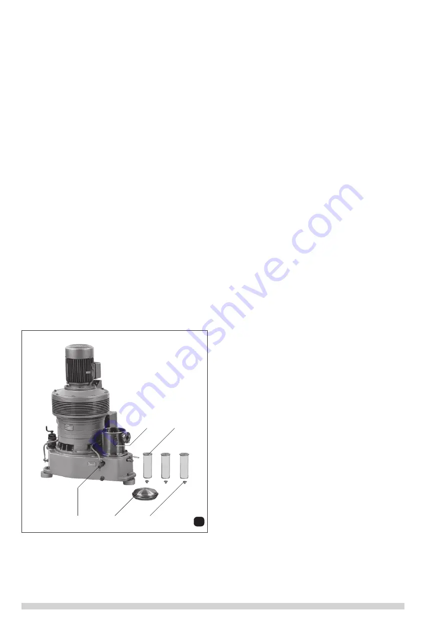
Exchange of candle filters: oil reservoir cap (d) and O-ring may
be removed by opening. Release retaining cap (m), exchange
candle filters (f) and check for correct fitting. The condensate
and oil mixture formed should also be discharged regularly,
manually or automatically, during operation of the pump. A level
monitor (V
1
) is normally fitted, to switch off the pump automati-
cally at the appropriate level.


