13–13–600 Page 11
3.
Elevation of the oil cooler above the compressor
unit.
4.
Pipe type and size(s) to be used to connect the oil
cooler and the compressor unit. Minimum pipe
size is 2–1/2” NPT.
5.
Horizontal and vertical lengths of the pipe run. If
more than one pipe size is used, list length of each
size and total length.
6.
Number and size of elbows, tees, unions, reduc-
ers, and valves to be used in the pipe run.
7.
A dimensional sketch of the proposed piping sys-
tem showing location of the compressor unit, oil
cooler, pipe, and fittings illustrating design in-
formation included in numbers 3 through 6 above.
All remote piping should be of adequate size to insure
a minimum pressure loss. Number 4 above lists the
minimum pipe size to be used. Long runs of pipe and
the use of valves and fittings require larger than the
minimum pipe sizes in the system to keep the pressure
loss low. All pipe and fittings used in a remote oil cooler
system should be galvanized or treated internally to
prevent rust, and all valves are to be of a nonferrous
construction to prevent corrosion and fouling.
The remote cooler should be placed so that the fan air
flow through the cooler (air flow is from the motor side
through core) and the prevailing winds are in the same
direction. A baffle should be provided on the exhaust
side of the cooler for protection against occasional wind
shifts.
When the oil cooler is mounted above the compressor
unit, a check valve is to be mounted on the compressor
unit in the line to the oil cooler; see FIGURE 5–3, page
34. A pneumatic pilot–operated normally–closed valve
(oil stop valve) is to be mounted at the oil filter inlet on
the compressor unit line from the oil cooler. The check
valve permits oil flow to the oil cooler during operation,
but prevents return oil flow from the cooler when the
unit is shut down. The pilot valve is held open by air
pressure from the unit oil reservoir during operation and
closes under spring load when the unit is shut down to
prevent return oil flow from the oil cooler. A different
control group will be assembled onto the package to
control the oil stop valve and to prevent the compressor
package from running in low demand mode. Failure to
install these parts could result in high oil carryover and
could cause the machine to shut down on high temper-
ature.
An oil filler stand pipe and plug must be located in the
piping on the oil cooler module for ease of filling of a re-
mote oil cooler, see FIGURE 5–2, page 32.
Oil Cooler – Installation – Inspect unit upon arrival.
In case of damage, report immediately to transporta-
tion company. Before installation, check rating plate on
motor to verify that power input and motor specification
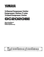
FIGURE 2–5 – COOLER DRAIN DETAIL
requirements match available electric power at point of
installation.
1.
Set the unit level on a firm, solid foundation. The
larger oil cooler models have lifting holes to facili-
tate unit hoisting.
2.
Allow for linear expansion and contraction of pip-
ing in the direction away from the oil cooler. Use
flexible connectors or suitable expansion joints on
all oil cooler inlet and outlet piping. See
FIGURE 2–3, page 9, for typical schematics.
3.
Select properly tensioned and aligned piping sup-
port clamps or hangers and position them to re-
lieve any piping stress at the oil cooler inlet and
outlet ports. Do not support from flexible connec-
tors.
4.
Service – For continuous efficiency, oil cooler
cores must be periodically cleaned with either
vacuum or compressed air. If wet cleaning is re-
quired, shield motor and spray on a mild soap
solution and flush with clear water.
AUXILIARY AIR RECEIVER – The unit requires an
auxiliary air receiver unless the piping system is large
and provides sufficient storage capacity to prevent rap-
id cycling. When used, an air receiver should be of ade-
quate size, provided with a relief valve of proper setting,
a pressure gauge, and a means of draining conden-
sate.
AFTERCOOLER (FIGURE 1–2 and FIGURE 1–5,
pages 2 and 3) – An aftercooler will provide control of
moisture entering the shop air lines while reducing the
Summary of Contents for ELECTRA-SAVER ETY99A
Page 14: ...13 13 600 Page 6 DECALS 206EAQ077 212EAQ077 218EAQ077 211EAQ077 207EAQ077...
Page 15: ...13 13 600 Page 7 DECALS 216EAQ077 217EAQ077 222EAQ077 221EAQ077 208EAQ077...
Page 29: ...13 13 600 Page 21 FIGURE 4 1 SCHEMATIC TUBING DIAGRAM 302ETY797 A Ref Drawing...
Page 34: ...13 13 600 Page 26 FIGURE 4 8 CONTROL SCHEMATIC COMPRESSOR AT FULL LOAD 304ETY797 A Ref Drawing...
Page 37: ...13 13 600 Page 29 FIGURE 4 11 WIRING DIAGRAM 302ETY546 Ref Drawing...
Page 39: ...13 13 600 Page 31 FIGURE 5 1 FLOW DIAGRAM 303ETY797 A Ref Drawing...
Page 58: ...Specifications subject to change without notice Copyright 1998 Gardner Denver Machinery Inc...