


13–10–613 Page 33
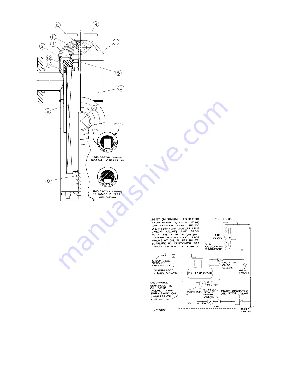
FIGURE 5–4 – COMPRESSOR OIL FILTER
check its inside bore for burrs or deep scratches
and carefully smooth out if required. Check seal
(13) for cuts and excess wear.
4.
Remove element (6) from housing assembly (3).
Remove indicator assembly (5) from element (6)
by inserting screwdriver between indicator as-
sembly and element cap and carefully prying
downward. Inspect indicator O–ring (4) for cuts or
excessive wear and discard element (6).
5.
Remove O–ring from head assembly (1) and in-
spect for cuts or excessive wear. Wipe O–ring
area of head (1) with clean cloth and after covering
O–ring (2) with oil, reinstall in head assembly.
6.
Reinstall indicator assembly (5) into new element
(6). Place element into cannister (3), making sure
that large diameter of spring (8) contacts the new
element, and install baffle (12).
7.
Place head assembly (1) onto housing assembly
(3) and rotate tee handle (9) clockwise until hand
tight; do not exceed 20 foot–pound torque if tools
are used.
8.
Reconnect starter to power source.
9.
If leakage appears around tee handle (9) remove
snap ring (11) and remove tee handle (9) from
head assembly (1). Remove O–ring (10) and in-
spect for nicks or cuts and replace if necessary.
Wipe tee handle (9) and O–ring groove. Then oil
and replace O–ring (10), insert tee handle (9) into
head assembly (1) and replace snap ring (11).
BEARING OIL FILTER – An oil filter of the spin–on
type is used. This filter is a vital part in maintaining a
trouble–free compressor, since it removes dirt and
abrasives from the circulated oil before it reaches the
bearings. The filter is the disposable type and is
equipped with a relief valve that opens in the event the
element becomes dirty enough to block the flow of oil.
The filter must be replaced each time the main oil
filter element is replaced. When changing this filter
between oil changes, add one (1) quart of lubricant to
the system to replace that retained in the old filter. Use
only the replacement filter shown in the parts list, as
others may not have sufficient burst pressure strength.
To replace filter, stop the unit and be sure no air pres-
sure is in the oil reservoir. Disconnect, tag and lockout
power supply to the starter. Spin off the old filter and
discard, then spin on the new filter by hand, tightening
firmly enough to prevent leaks.
COMPRESSOR OIL COOLER – RADIATOR TYPE
(FIGURE 5–5) – The air–cooled oil cooler module is re-
mote mounted. The oil cooler requires pipe and electri-
FIGURE 5–5 – OIL FLOW DIAGRAM –
REMOTE OVERHEAD MOUNTED OIL COOLER
Summary of Contents for ELECTRA-SAVER EAY
Page 14: ...13 10 613 Page 6 DECALS 206EAQ077 212EAQ077 218EAQ077 211EAQ077 207EAQ077...
Page 15: ...13 10 613 Page 7 DECALS 216EAQ077 217EAQ077 222EAQ077 221EAQ077 208EAQ077...
Page 32: ...13 10 613 Page 24 FIGURE 4 8 CONTROL SCHEMATIC COMPRESSOR AT FULL LOAD 204EAY797 B Ref Drawing...
Page 35: ...13 10 613 Page 27 FIGURE 4 11 WIRING DIAGRAM 202EAY546 Ref Drawing...
Page 55: ......


