background image

Page 13

4990140010   Date:03/15

XK12 Installation, Operating & Maintenance Manual

Page 13

4990140010   Date:03/15

XK12 Installation, Operating & Maintenance Manual

Installation

3.8 Ancillaries 

(relating to fi gures 10a - 10b)

Inlet Air Filter and Flexible Induction Kit

Should be located so that the inlet air is cool and clean. Do not mount close to exhausts or 
other warm air sources. Ensure screw-on cuff s are sealed onto inlet hose using suitable high-
temperature silicone sealant, such as DOW CORNING Silicone AP.
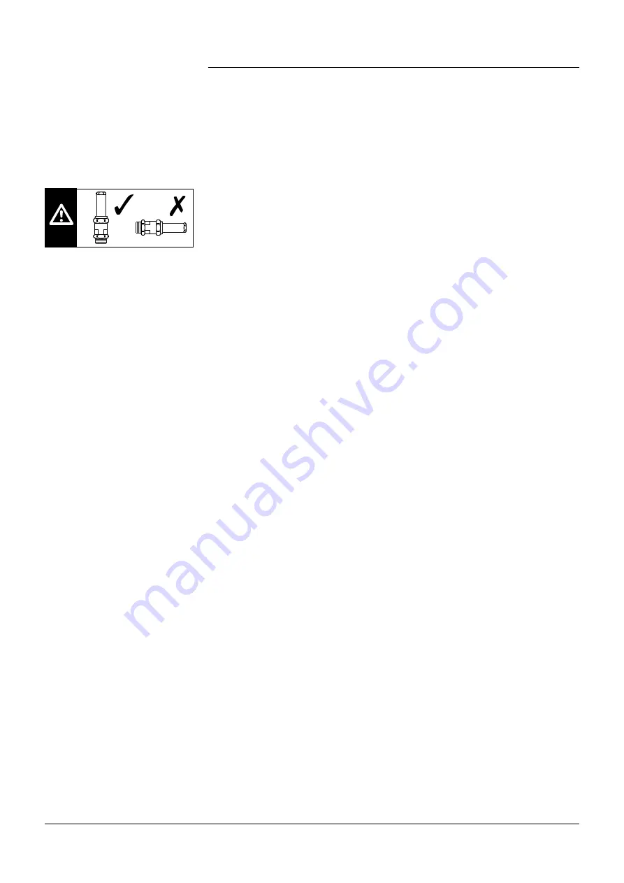
Relief Valve

The relief valve is installed to prevent the XK12 from encountering pressures beyond its 
operating range.

The relief valve should be installed as close as possible to the discharge port of the machine 
prior to any other discharge ancillary and should be mounted vertically (as shown in fi g 10 ).

It is pre-set, wired and leaded (tamper proof ) and fi tted to protect the XK12 (rather than the 
system which should be protected by the vehicle tank relief valve) against pressures of over 
2.5bar g . Adjustment of the machine relief valve will invalidate the XK12 and relief valve 
warranty.

Discharge Silencer

Should be mounted/connected as close as possible to the discharge port (after the relief valve) 
utilising the slip-on-weld fl anges supplied.

Silencers should be mounted/supported separately to prevent the generation of loads on 
the machine and discharge port due to weight or temperature expansion. Flexibility in the 
mounting or connecting pipe work to the silencer should be incorporated where this could 
occur.

Check (non-return) valve

This is to prevent a back-fl ow of air and product (often encountered when stopping 
compressors whilst the discharge tank is still pressurised) from entering and damaging the 
XK12. 

The check valve should be the last ancillary on the discharge pipework (but before any regular 
disconnection point) to protect all the other ancillaries. It is often mounted directly to the 
delivery port of the discharge silencer.

If the check valve has to be mounted horizontally on the silencer or separately, the check valve 
hinge should be positioned at the top in horizontal pipe work to encourage closure under 
gravity. If mounted vertically, the position of the check valve hinge is not important.

Torque Coupling

We recommend and supply a torque-limiting device for fi tting to the compressor when direct 
PTO driving.

This is to protect all the drive-line equipment against the possibility of high torque during 
operation for any circumstances.

Expansion Joints

Any pipe work or equipment should incorporate fl exible elements where:


• Movement due to thermal expansion is likely


• Pipe work crosses the vehicle chassis.

Ball Valve

A 1“ - 1.5” manual ball valve must be fi tted on the discharge side of the machine between the 
compressor discharge port and the check valve.

This allows the compressor discharge air to vent to atmosphere to prevent the machine being 
started against a pressurised tank.

Comissioning Filter 

See section 3.7

Fig 10. Relief valve orientation

Summary of Contents for DRUM XK Series

Page 1: ...XK SERIES SCREW COMPRESSOR Models XK12 XK12HD Installation Operating Maintenance Manual Original Instructions 4990140010 2015...

Page 2: ...ive alignment 10 3 6 Pipe work 12 3 7 Commissioning filter 12 3 8 Ancillaries 13 3 9 Package 1 layout parts 14 3 10 Package 2 layout parts 15 4 Operating and Commissioning 4 1 Pre commissioning check...

Page 3: ...work as close to the compressor as possible The valve must be positioned so as not to vent air onto any personnel since the air discharged will be hot and can cause severe burns Storage Low use Befor...

Page 4: ...s to enable low cost prop shaft driving A through shaft allows CW or ACW input drive rotation with mounting points on either side of the machine to provide further flexibility The standard compressor...

Page 5: ...ard ancillaries supplied as separate items including the absorptive type discharge silencer and cyclonic inlet filter kit Package 2 Loose ancillaries with reactive discharge silencer Standard ancillar...

Page 6: ...149 Nm on the high speed XK12 Speed range 1810 2896 rpm Operating environment The permissible foreseen operating environment is as follows Ambient temperature range 40 to 50 C Resistant to tropical ra...

Page 7: ...to the XK12 discharge port Venting valves must be positioned so that hot air cannot vent onto the operator or the compressor Silencers should be fitted as close as possible to the discharge port For t...

Page 8: ...path possibilities are shown below Installation Figure 4 Mounting Drive options An incorrect drive rotation will damage the compressor CAUTION Outlet Alternative Outlet Inlet The basic XK12 compresso...

Page 9: ...pproximately 1 5 litres total if necessary Key 1 Fill Plug washer 2 Fill Level Plug 5 Magnetic Drain Plug 3 Plug Cap 4 Drain Plug washer Figure5 MountingDetails separateancillarypackages Alternative m...

Page 10: ...ction 3 8 torque coupling for recomendations on couplings for PTO drives Before fitting the tapers on the machine shaft and drive coupling should be clean and damage free to help ensure the flange fit...

Page 11: ...Friction Coupling A B C A D E F G H I E A J C K C L M N N O P Q R S Q T U V T W X Y Q U Z _ Y W a O Y b U Z a c d N e Q U Z f b X S T P g N h b i j a P k N l a m n b P b Y Y a Y e a R S b U Z W Y b P...

Page 12: ...points should be followed to prevent damage to the machine and contamination of the discharged product All inlet pipe work must be stainless steel or thick wall aluminium to help prevent corroded part...

Page 13: ...rature expansion Flexibility in the mounting or connecting pipe work to the silencer should be incorporated where this could occur Check non return valve This is to prevent a back flow of air and prod...

Page 14: ...ied item Indicates customer supplied pipework Ref No Description 1 XK 12 Basic M C or high speed unit 2 10 Cyclonic Inlet Filter 3 3 75 Hose Clip 4 Hose Adaptor Cuff Nitrile 5 Ducting 2m x 89mm Bore 6...

Page 15: ...unit 2 10 Cyclonic Inlet Filter 3 3 75 Hose Clip 4 Hose Adaptor Cuff Nitrile 5 Ducting 2m x 89mm Bore 6 Inlet Flange XK 12 7 Inlet gasket 8 Commissioning Filter XK 12 XK 18 9 Gasket Outlet Port 10 Out...

Page 16: ...ture probe and a pressure probe for commissioning only see Fig 11 If Gardner Denver Drum supplied flanges are not used the installer must provide 2 x 1 4 BSP tappings adjacent to the inlet and outlet...

Page 17: ...ris that may be present 4 After 15 minutes depress the clutch and engage the PTO 5 Check the oil fill level and drain plugs for leaks and replace the commissioning filter with the inlet gasket supplie...

Page 18: ...ng Maintenance Manual 3 4 5 3 4 7 8 8 7 2 6 1 Commissioning Figure 12 Commissioning Tests No Description 1 Pressure Manometer 2 Temperature Gauge 3 Pressure Tapping Inlet depression 4 Temperature Tapp...

Page 19: ...from discharge line prior to the check valve When the compressor reaches operating speed the line can be slowly closed again to restart delivery Starting the compressor Check that the PTO is disengag...

Page 20: ...e and should include Safety Instruct the driver regarding Rotating parts Hot Pipework Safety valve Safety coupling Operation Instruct the driver regarding Speed range Maximum operating pressure PTO en...

Page 21: ...RIAL NO DATE COMMISSIONED CUSTOMER VEHICLE REG VEHICLE MAKE VEHICLE MODEL PTO TYPE RATIO ENGINE SPEED COMMENTS TIME DURATION INPUT SPEED Rpm PRESSURE BAR g BARO m bar INLET DEPRESSION RELIEF VALVE LIF...

Page 22: ...ble 1 3 l min should be at least possible NOTE 500 hours is the maximum oil change interval NOTE Drive systems must be maintained in accordance with the manufacturers instructions Daily Check Air Filt...

Page 23: ...ster With the compressor operating at greater than 85 of its pressure setting Setting 85 2 bar g 1 7 bar g 2 2 bar g 1 87 bar g 2 5 bar g 2 25 bar g Operation Function Test 1 Rotate the lifting screw...

Page 24: ...e Empty out any dust or dirt and then re fit in the original position vacuator valve downwards Cleaning the element The air filter is fitted with a blockage indicator to show when the filter requires...

Page 25: ...ervice Maintenance Record for XK12 Compressor Serial Number MONTH 1 2 3 4 5 6 7 8 9 10 11 12 Oil Level Relief valve Air Filter Security MONTH DATE DATE DATE DATE DATE Oil Change Air Filter Check Valve...

Page 26: ...d Seven Hills New South Wales 2147 Australia Phone 61 2 96207000 Fax 61 2 96207955 email hermant malik gardnerdenver com France Gardner Denver France SA Division Compresseurs 42 rue du Montmurier BP 6...

Reviews: