background image


HOT ENGINE STARTING 


Set the ignition switch Fig 35 to the 


Pull the starter rope until the engine starts.


If the engine does not start after 5 pulls, use the cold start procedure. 


  OVERCHOKING 


Should the engine become flooded due to over
unscrew the spark  plug, wipe  it dry or replace, pull the  recoil starter several times  without the  spark plug  in 
place and with the choke in the open 

STOPPING THE ENGINE 


Set the engine to idling by releasing the throttle lever.


Set the ignition switch to the 

STOP (O)


If the engine fails to stop, set the choke lever to
until the ignition switch is repaired.


RUNNING IN


During the first ten hours of work, avoid running the engine at maximu
the components have bedded in.   

MAINTENANCE   


IMPORTANT 


After every use, check that all nuts, bolts and screws are securely fastened and tighten if necessary.


FUEL FILTER 


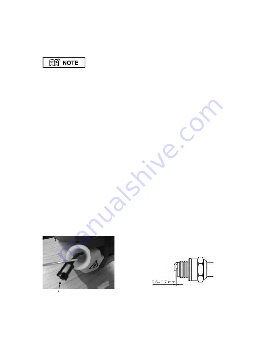
Every  15  hours  of  operation,  using  a  wire  hook,  take  the  fuel  filter  from  the  fuel  tank  Fig  36  and  clean  or 
replace with a new fuel filter.


Fig 36 


fuel filter 


Set the ignition switch Fig 35 to the 

START ( I )

 position. 

Pull the starter rope until the engine starts. 
If the engine does not start after 5 pulls, use the cold start procedure.   

the engine become flooded due to over-choking set the ignition switch to the 

STOP (O)

unscrew the  spark plug, wipe it  dry or replace,  pull the recoil starter several times without  the spark  plug  in 
place and with the choke in the open position. This will help clean and ventilate the combustion chamber.

Set the engine to idling by releasing the throttle lever. 

STOP (O)

 position Fig 35. 

If the engine fails to stop, set the choke lever to the closed position to stall the engine; do not use the machine 
until the ignition switch is repaired. 

During the first ten hours of work, avoid running the engine at maximum speed for a prolonged 

  After the engine has been run-in, it will reach its maximum power.

After every use, check that all nuts, bolts and screws are securely fastened and tighten if necessary.

using  a  wire  hook,  take  the  fuel  filter  from  the  fuel  tank  Fig  36  and  clean  or 


Fig 37 

STOP (O)

 position Fig 35, 

unscrew the  spark plug,  wipe it  dry or replace,  pull the recoil starter several times without  the spark  plug in 

position. This will help clean and ventilate the combustion chamber. 

the closed position to stall the engine; do not use the machine 

m speed for a prolonged period until all 

maximum power. 

After every use, check that all nuts, bolts and screws are securely fastened and tighten if necessary. 

using  a  wire  hook,  take  the  fuel  filter  from  the  fuel  tank  Fig  36  and  clean  or 

Summary of Contents for GCMT262

Page 1: ...Gardencare User Manual 1110CA VI OWNER S MANUAL GCMT262 MULTI TOOL READ THIS MANUAL CAREFULLY BEFORE OPERATING THE MACHINE WARNING THIS SYMBOL INDICATES IMPORTANT SAFETY FEATURES...

Page 2: ...ever 6 Ignition switch 7 Harness hanger 8 Loop handle 8A Rubber hand grip 9 Transmission shaft 10 Attachment shaft 11 Safety guard 12 Gear box 13 Nylon head 14 Optional cutting blade 15 Cutting blade...

Page 3: ...ING OF THE L HANDLE 5 ASSEMBLY OF THE BRUSH CUTTER 6 ASSEMBLY OF THE PRUNER 9 HEDGE TRIMMER ATTACHMENT 13 ATTACHING THE TOOLS TO THE DRIVE SHAFT ASSEMBLY 14 OPERATION 15 TWO STROKE FUEL 15 STARTING TH...

Page 4: ...ear defenders Wear security shoes and gloves Beware Keep hands and feet away from moving parts Always keep a safe distance from the cutting parts Hot surface Risk of burn Danger Risk of intoxication...

Page 5: ...perimeter of 15 metres of the work area should be considered a hazardous area into which no one should enter while the multi tool is being used and when necessary this area should be marked with a wa...

Page 6: ...l grip the handles firmly with both hands place your feet slightly apart so your weight is distributed evenly across both legs and always maintain a steady even posture while working Maintain full eng...

Page 7: ...ey Fig 3 Fig 5 PLASTIC GUARD HOLDER A ASSEMBLY OF THE BRUSH CUTTER The blade fitted to the guard is sharp and can cause injury always wear gloves Lay the brush cutter on its back with the gearbox shaf...

Page 8: ...the blade Lay the brush cutter on its back with the gearbox shaft facing up Rotate the gearbox shaft until the hole in the holder A lines up with the slot in the plastic guard Fig 5 Insert the Allen...

Page 9: ...serious damage you must replace the complete nylon head Open the nylon head by pushing on the catch Fig 13 and twisting the cover anti clock wise Pull the bobbin out of the nylon head and take out the...

Page 10: ...he engine speed so the engine idles cutting head has stopped rotating switch off the engine and remove the material Put the machine on the ground and check that the cutting head has not been damaged I...

Page 11: ...aw CHECKING THE OIL SUPPLY After starting the engine run the chain at medium speed and see if chain oil is thrown off as shown in the figure Fig 23 ADJUSTING OIL FLOW RATE Never fill the oil reservoir...

Page 12: ...hain needs to be sharpened when Sawdust becomes powder like You need extra force to saw The cut does not go straight Saw chain sharpening Be sure to wear safety gloves Remove multi tool from power uni...

Page 13: ...e the affects of kickback and pinching as well as maintain control of the machine Cut at high engine speeds Follow the manufacturer s instructions for sharpening and maintaining the chain Use only gen...

Page 14: ...multi tool Adjusting the angle of the cutting blades 1 Stop the engine 2 Turn the clamp bolt located on the top of the trimming mechanism counter clockwise to loosen it 3 Adjust the angle of the blade...

Page 15: ...pruner When carrying by hand the bar ch 2 1 ATTACHING THE TOOLS TO THE DRIVE SHAFT ASSEMBLY Rest the power unit shaft assembly on a flat firm surface Ensure that the clamping wing nut 2 is loose pull...

Page 16: ...l as it can cause fouling of the spark plug exhaust port blocking piston ring sticking and other internal engine damage FUEL STORAGE Mixed two stroke fuel which has been left unused for a period of on...

Page 17: ...ter cord all the way out and do not let go of the starter handle when the cord is extended this can damage the starter mechanism Rest the unit on a flat firm surface Keep the cutting head off the grou...

Page 18: ...ngine become flooded due to over choking set the ignition switch to the STOP O unscrew the spark plug wipe it dry or replace pull the recoil starter several times without the spark plug in place and w...

Page 19: ...sary Fig 37 tool check the air filter Fig 39 Being clogged will reduce the engine performance Remove the air filter cover by undoing the cover screw Fig 38 clean the filter element in warm soapy water...

Page 20: ...OTTLE LEVER The safety lock is to prevent the throttle lever from accidentally being engaged The throttle lever Fig 41 can only be pressed in if the safety lock is held down Check if the safety lock a...

Page 21: ...ade thickness Cutting line diameter Max blade rotation speed Rotation direction Air cooled 2 stroke petrol engine IE34F 2E 25 4 cc 0 7 kw in accordance with ISO 8893 2800 150 Max power speed rpm min 1...

Page 22: ...ratio 4 1 Cutting head Type Reciprocating Double blade Tooth 28 teeth Pitch 30mm Effective cut width 16 inches 400mm Angle adjust range 90 45 from cutting head position aligned shaft EX PS When used w...

Page 23: ...of the product Spare parts that are subject to wear e g safety parts blades blade supports bearings cables guards deflectors spark plugs air filters etc Neither does warranty extend to Freight and pac...

Reviews: