17
GB
Connecting your Watering
Controller :
8
9
B
F
E
0
A
G
C
D
C
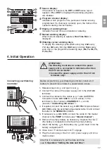
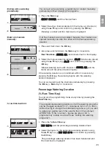
Sensor display :
If the sensor is inserted, the
DRY
or
WET
status report
appears. When
WET
is displayed the watering programs
are disabled.
D
Program / channel display :
Indicates which program of the particular channel is being
programmed. If a channel is currently open, the frame of the
opened watering channel flashes.
E
Display of watering times :
Indicates the start time and duration of watering.
F
Manual watering display :
When manual watering is selected,
Run Time Man.
is
displayed.
G
Watering cycles / watering days :
To display the watering cycles (
24 h
every day,
2nd
every
2nd day,
3rd
every 3rd day,
Odd
every odd day
Even
every
even day) or the programmed watering days (
Mo, Tu, We, Th,
Fr, Sa, Su
).
4. Initial Operation
ATTENTION !
A
The Watering Controller is ruined if the power
supply unit is connected to terminals other than
the 24 V AC terminals !
V
Connect the power supply unit to the 24 V AC
terminals only !
Before programming your Watering Controller, install a 9-V
battery to prevent loss of data if a power failure occurs.
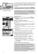
1. Release snap lock
1
and open cover
2
.
2. Connect the cable of the power supply unit to the
24 V AC
terminals.
3. Connect the cables for the valves (e.g. 7-wire GARDENA
Connection Cable
Art. 1280
for up to 6 valves) to the
terminals for the channels (
CHANNELS 1…
) and
C
(see also
“Connecting the valves”
).
4. If required, connect the sensor (e.g. GARDENA Moisture Sensor
Art. 1188
) using the accompanying adapter cable
z
S
and connect
the latter to the
SENSOR
terminals.
5. If necessary (e.g.
Art. 1273
) connect the cable for the master
channel to the
PUMP
terminals (see
“Master channel”
).
6. Remove the empty battery as necessary : Depress the clip
z
L
(the battery is released) and remove the empty battery.
7. Attach the battery
3
to the battery clip
4
and insert it into the
battery compartment
5
.
8. Close cover
2
and let snap lock
1
engage.
9. Plug the mains plug of the 24 V (AC) power supply unit into a
mains socket.
After this it is necessary to set the date and time
(see
5. Operation “Setting the date and time”
).
1
2
5
3
z
S
z
L
4


