8
ASSEMBLY INSTRUCTIONS
Hardware Used
Hardware Used
Hardware Used
2
I
BB
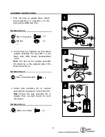
1. With the base (I) upside down, attach
wheel assembly (J) using M8 x 15 mm
bolts (AA) and M8 nuts (CC).
2. Turn the base (I) right-side up, then attach
cylinder assembly (H) using M5 x 8 mm
black bolts (BB) though preassembled
L-pins.
Note:
The door on the cylinder assembly
(H) should be on the opposite side of the
wheel assembly (J).
3. Attach pole assembly (D) to cylinder
assembly (H) using M6 x 10 mm bolts (FF).
Note:
Ensure the pole assembly (D) is
straight. Then, use deck ring (G) to cover
connection.
X 2
X 2
M8 Nut
M8X15mm Bolt
AA
CC
1
J
K
AA
CC
M8 x 15 mm Bolt
M8 Nut
x 2
x 2
X
5
BB
M5 X 8mm Bolt
M5 x 8 mm Black Bolt
x 5
FF
M5 X 10 mm Bolt
X
4
M6 x 10 mm Bolt
x 4
H
FF
D
Back
3


