background image

9

4.1 PROGRAMMING WITH MECHANICAL LIMIT SWITCH

ATTENTION

: to let the safeties work, these must be connected 

before

 starting the control unit setup. 

Setup process - Mechanical limits standard

1

Set DIP10 in OFF position for selecting mechanical limits and DIP1 and DIP2 to OFF position for deadman operation. 

Standard control for mechanical limits are for PNE edge type (3-4 terminals on X5) and no photo connected.

ATTENTION: Switching DIP10 to ON position and back to OFF will reset to mechanical standard with ONLY PNE edge 

type.

2

Press OPEN or CLOSE to the desired close and open limit position and adjust cam until the limit is correct.

Note: if door is moving in the wrong direction the 2 phases on the mains connection must be interchanged.

3

Limits are now adjusted.

Check that the safety edge is working (if mounted).

Setting process - Mechanical limits with other safety connected

ATTENTION: additional safeties as OSE (connected to X5 5-6-7) or photocell (connected to X6 9-10-11-12)

will be active only after the setting process

4

Make setup process 1 and 2 and move the door away from close limit.

5

Connect the requested safeties.

Activate setting by pressing OPEN+STOP for about 10 sec then release. The red LED FAIL (PCB) start with 2 short flashes

6

Press STOP to stop setting the edge type and photo. Yellow LED SPEED/SER confirming with 1 sec

7

Limits are now adjusted and edge type and photo circuit are memorised. Check that the safety functions are working as 

expected.

ATTENTION: moving DIP10 to ON position and back to OFF will reset to mechanical standard with ONLY PNE edge type.

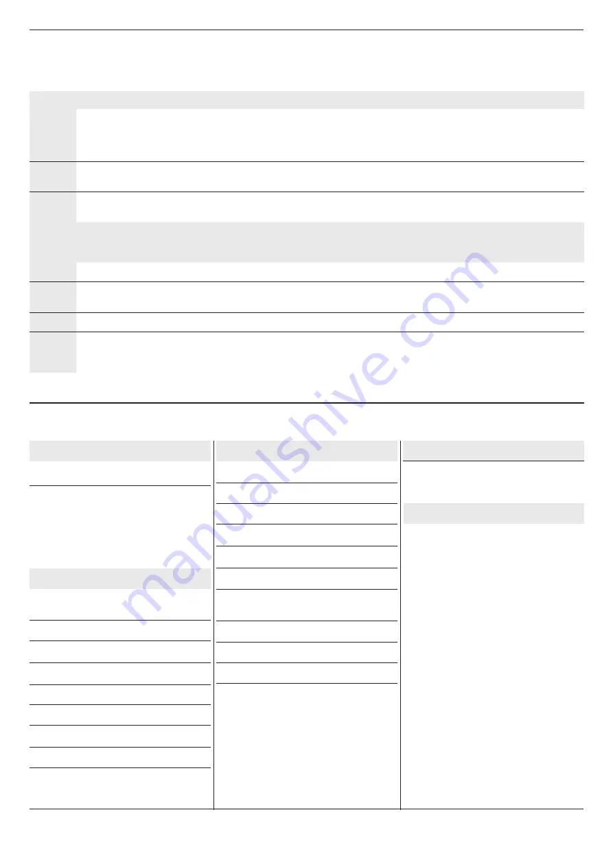
Yellow LED CONF./SER. (PCB)

Fixed light

Service needed (open 

counts reached)

1 sec. flash

Confirming learning 

process

Green LED POWER (PCB)

Fixed light

The controller is powered

Red LED CIRCUIT ERROR (PCB)

Fixed light

PCB circuit error fail

Red LED FAIL (PCB)

Fixed light

If Photo or Edge is activated 

when CLOSE pushbutton is 

activated

1 long flash

Auto close learning active

2 short flashes

Limits, edge and photo not 

learned

2 long flashes

Force control (speed) not 

learned

3 long flashes

Door stopped by force control

4 long flashes

Door stopped by runtime

5 long flashes

Door stopped by force control 

wear

6 long flashes

Tacho failure – pulses missing

Continues long

flashes

Fail state PNE edge monito-

ring. Check impuls by floor 

missing.

Yellow LED STOP (PCB)

Fixed light

Stop activated or both limits 

are active

1 long flash

Safety chain activated

2 long flashes

Photo – safety test failed.

3 long flashes

Safety edge – safety test 

failed.

4 long flashes

Stop circuit – safety test 

failed.

5 long flashes

Safety chain – safety test 

failed

6 long flashes

EEPROM failure. Elec. 

Counter or position counter by 

force control

7 long flashes

EEPROM failure. Powerup 

failure

8 long flashes

Welded contactor fail

9 long flashes

Internal watchdog timeout.

10 long flashes

Main processor crystal fail

4.2 LED GUIDANCE

Summary of Contents for QC400

Page 1: ...PANTONE 302C RAL 5000 C 100 M 30 Y 0 K 50 PCB VERSION 7 0217 R1717 VERSION SOFTWARE V05_00 QC400 Automatic control unit for three single phase motors with digital or mechanical limits...

Page 2: ......

Page 3: ...reparation or a maintenance job is required KEEP THIS INSTRUCTIONS Warning it is highly recommended to activate the impulsive mode only after having completed the set up and adjustments of the contro...

Page 4: ...mS when not 50 duty cycle Photo input X6 9 10 11 12 Photo 24 VDC e g self contain photo cell Performance level C Category 2 Electronic limits RS485 Data Data terminated with 120 Ohm Designed for Dalm...

Page 5: ...CAL LIMIT SWITCHES CLOSE LIMIT OPEN LIMIT CL OL COM S4 STOP BUTTON CLOSE BUTTON S2 OPTION SWITCH CONN BROWN GREEN WHITE QCLSM PLUG IN TRAFFIC LIGHT OPEN CLOSE PUSHBUTTON BOX PNE 8k2 YOU MUST CONNECT O...

Page 6: ...and put at risk the safety of the installer If you need to disconnect the power cable and then to reconnect it or change the control unit wiring sequence you HAVE TO connect the wires properly restor...

Page 7: ...d the auto close time is adjusted back to 15 Sec Auto closing time is remembered after power OFF Auto closing can also be disabled with a switch connected to X16 connector E When DIP4 is in ON positio...

Page 8: ...t the QC400 with a motor with mechanical limits set the DIP10 on S3 in OFF See 4 1 PROGRAMMING 1 GREY OPEN LIMIT SWITCH 2 GREEN OPEN BUTTON Micro on motor limit switch 3 WHITE SAFETY 4 YELLOW CLOSE BU...

Page 9: ...1 sec 7 Limits are now adjusted and edge type and photo circuit are memorised Check that the safety functions are working as expected ATTENTION moving DIP10 to ON position and back to OFF will reset...

Page 10: ...safety of peo ple and or things In order to connect the QC400 with a motor with electronic limit switch 1 Remove the 3pins white terminal from the cable our part FLCE31W012 Fig 1 2 Peel the 3 wires a...

Page 11: ...ing setting process Green LED POWER PCB Fixed light The controller is powed Red LED CIRCUIT ERROR PCB Fixed light PCB circuit error fail Red LED FAIL PCB Fixed light If Photo or Edge is activated when...

Page 12: ...ON 20 ms before motor contactor is turned OFF for activating the brake a brief time before motor stops 7 FLASHING LIGHT CONNECTIONS only for 3phase power supply 1 2 3 4 5 6 7 8 9 10 11 12 13 14 15 X5...

Page 13: ...onnected Pin 4 connected to board 24V after stop circuits Pin 5 connected to GND on board supply Pin 6 connected to 24 power on board supply Pin 7 10 Not connected NOTE the entrance GO terminals 11 12...

Page 14: ...X5 11 12 DIP7 ON Go function when photo safety is connected to controller When Door is not open or closed the door will do opposite of last When door is open the door will start closing When door is...

Page 15: ...15...

Page 16: ...0119 Gaposa srl via Ete 90 63900 Fermo Italy T 39 0734 220701 F 39 0734 226389 info gaposa com www gaposa com...

Reviews: