background image

21 

PTZ

PTZ

PTZ

PTZ


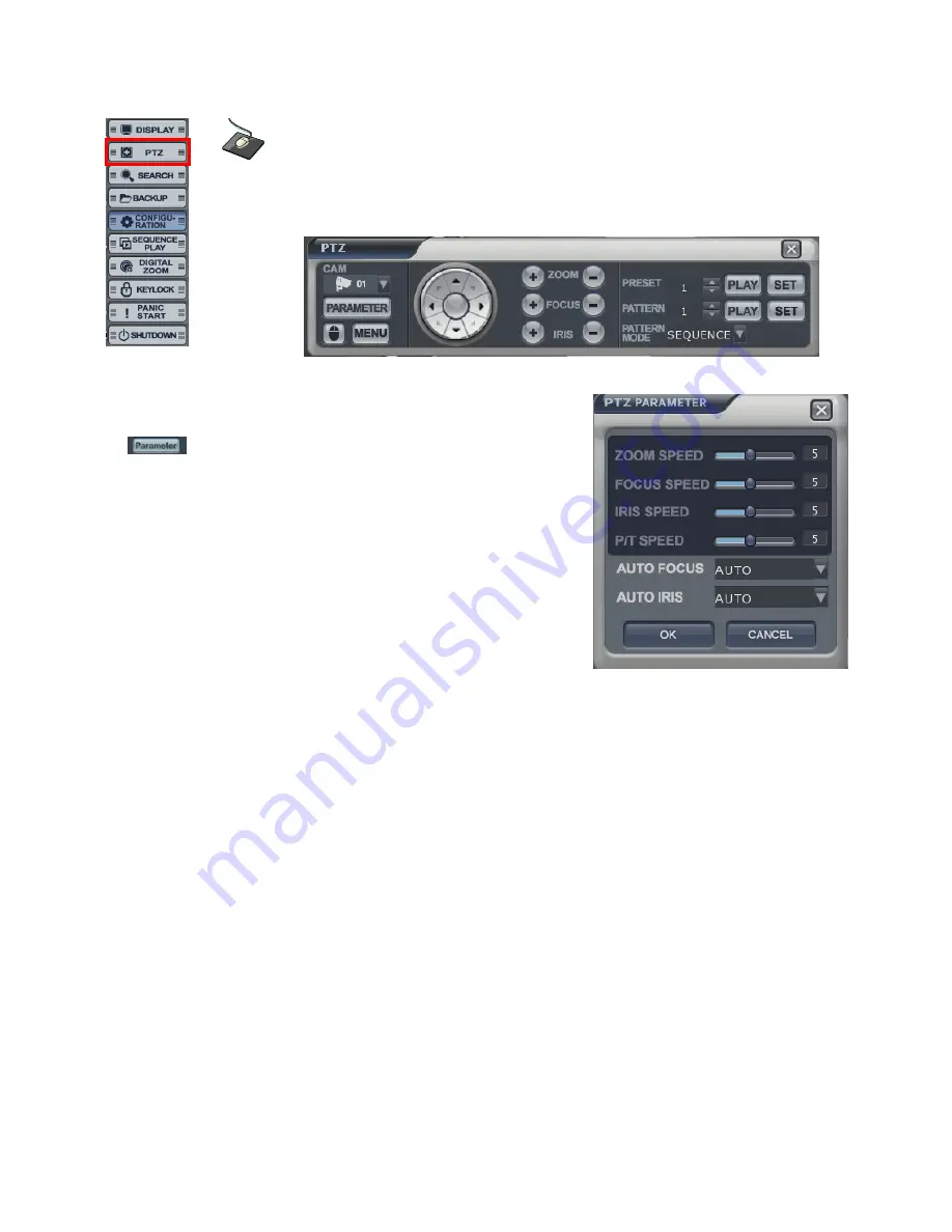
 PTZ controls appear like above.   

    1) Select the camera. 

    2) Control the camera direction. 

    3)                    Press this button. The operator can control the PTZ   

              detailed configuration with pop-up screen. 

    4) Control the Zoom, Focus, Iris. 

    5) Assign the Preset. 

            After moving the location, select the number   

and press the [SET] button.   

Camera will move as assigned location   

when pressing the [PLAY] button after selecting the number”. 

    6) Assign the Pattern. 

            After selecting the number, click the [PLAY] button. 

Pattern Mode 

- SEQUENCE PATTERN 

      Set preset position. [Move to any position by direction keys and click the [SET] button. 

      Select [SEQUENCE] in 

PATTERN MODE.


      To make starting position, click the [SET] button in 

PATTERN

. ([SET] button is activated.) 

      Select preset Number in 

PRESET

 and click the [PLAY] button. (Have to select more than two preset) 

      ex) select preset No 1 and click the [PLAY] button. Next select preset No 2 and click the [PLAY] 

  button.   

      To make stop position, click the [SET] button in 

PATTERN.

 ([SET] button is not activated.) 

      To run, click the [PLAY] button in 

PATTERN.


-CRUISE PATTERN 

      Select [CRUISE] in 

PATTERN MODE.


      To make start position, click the [SET] button in 

PATTERN.

 ([SET] button is activated.) 

      Click the direction key by manually. 

      To make stop position, click the [SET] button again in 

PATTERN

 ([SET] button is not activated.).   

      To run, click the [PLAY] button in 

PATTERN.


Click  the  right  mouse  button  on  the  Live  Display 

screen to click the 

PTZ 

PTZ 

PTZ 

PTZ 

menu. 

Summary of Contents for DR8NRT

Page 1: ...1...

Page 2: ...DVD DVD DVD DVD RW Connect RW Connect RW Connect RW Connect 18 Power On Power On Power On Power On 19 Live Display Live Display Live Display Live Display 20 Configuring the live display 20 PTZ PTZ PT...

Page 3: ...n RemoteSW installation 64 System Requirement 64 Introduce 66 RemoteSW Local Setup RemoteSW Local Setup RemoteSW Local Setup RemoteSW Local Setup 66 local setup 68 RemoteSW Search RemoteSW Search Remo...

Page 4: ...names correct connection methods for supported domes or pan tilt receivers control devices peripheral devices and the system setup instructions It is important to note here that some features figures...

Page 5: ...of the following precautions before installing the DVR Avoid positioning the GANZ DIGIMASTER in any place where the unit may come into contact with moisture dust or soot Avoid placing in direct sunlig...

Page 6: ...6 The following are warnings and cautions to ensure user safety and prevent property damage Please read the information below thoroughly...

Page 7: ...7...

Page 8: ...8...

Page 9: ...9...

Page 10: ...venience receptacles and the point where they exit from the apparatus 11 Only use the attachments accessories specified by the manufacturer 12 Use only with a cart stand tripod bracket or table specif...

Page 11: ...omposite 75ohm unbalanced Display mode Full screen sequence adjustable dwell time Audio out Channels 1 Connection RCA line level unbalanced External alarm Inputs 16 16 Open collector TR NO or NC commo...

Page 12: ...Watchdog Yes Abnormal shutdown detection Yes with system auto recovery HDD error detection Yes SMART monitoring Network Connection RJ45 10 100 Ethernet DHCP Yes DDNS Yes Two way network audio Yes Band...

Page 13: ...s List ts List ts List ts List Please check if all the product contents are present after opening the package Basic Contents Remote Controller Instruction Manual Remote Agent Installation CD AAA Batte...

Page 14: ...ORIGANIZATION System Organization System Organization System Organization System Organization NETWORK Camera Alarm Sensor Relay Out VCR VGA Monitor A V Monitor Remote Client PC Image Printer Video In...

Page 15: ...ETUP Go to System Setup Menu SEARCH Go to Search Menu USB PORT USB Port for use of a USB Memory Stick and or USB HDD Backup Mouse left Click Mouse Right Click LED Indicator Indicates Present System St...

Page 16: ...minal Alarm 16 x Input TTL Alarm Sensor Input Terminal Relay 16 x Relay Output Terminal USB PORT USB Port for use of a USB Memory Stick and or USB HDD Backup VGA OUT VGA Main Monitor Output RS 232C Se...

Page 17: ...erent ID You can control all The DVR s from one controller by setting DVR ID on controller using the ID button POWER System ON OFF MENU Open System Setup Menu RETURN Mouse Left Click ENTER Mouse right...

Page 18: ...e after opening the top cover The connection board is in red box 1 is the port for system disk master disk Install the first HDD at this port HDD jumper location should be Master 2 is also the port to...

Page 19: ...button The DVR starts the normal operation and it shows default display of all 16channels Three pop up displays would show current system information live log and live alarm situation C Continuous Re...

Page 20: ...er system setup menu of configuration directly Configuring the Live Display Configuring the Live Display Configuring the Live Display Configuring the Live Display Display Type The operator could selec...

Page 21: ...t SEQUENCE in PATTERN MODE To make starting position click the SET button in PATTERN SET button is activated Select preset Number in PRESET and click the PLAY button Have to select more than two prese...

Page 22: ...ail E Each recording configuration would show in different color F Shows the recorded data Playback Date time Select the date When the date has recorded data it would show with color at F Select the t...

Page 23: ...rchiving Then it would show below screen During the playback the operator can save the AVI file for a certain period Input the archiving tag Select the channel Tick on LOG TEXT REC INDEX TABLE Input t...

Page 24: ...ge from backup Data Management of backup menu Click the button for full screen from D Then below screen would be shown For returning drag the mouse to the bottom of screen Then below icon would appear...

Page 25: ...ack display from D The operator can select the playback display mode The display color for the recorded data at Timeline from E appears differently for each type like above Playback Live View Select t...

Page 26: ...the what the operator desires Select the log For playing the recording data with log double click the log Click same button again to return to the original screen Page Down Page Up Oldest log and Lat...

Page 27: ...earch Sequence Search The operator can search frame by frame Select the channel Select the date Select the time The operator can select the time from timer or by dragging the timeline bar The method t...

Page 28: ...search with divided screens in each time range The operator can select the playback location by Drag and drop Timeline bar Select the channel Select the date How to search is almost same with normal s...

Page 29: ...Designated Accuracy of the Selected Area For example to detect the motion of appropriate location select area of the image Set the accuracy and interval designated time to detect the event Next start...

Page 30: ...Click the QUERY button Then it shows data information at BACKUP INFO Click the button to save the data after inputting the backup tag The operator can see the saved data from backup Data Management C...

Page 31: ...ata Management Backup Data Management Backup Data Management Backup Data Management The operator can see the saved snapshot image and AVI file form Backup menu and search menu Detailed information Del...

Page 32: ...mera Camera Camera Camera Title Title Title Title Camera Title Input the Title and description with virtual keyboard Click the right mouse button on the Live Display screen and Click the CONFIGURATION...

Page 33: ...Brightness Contrast Tint and Color The operator can control the color of the live display by clicking the button Camera Camera Camera Camera PTZ PTZ PTZ PTZ Select the address protocol and Baud rate o...

Page 34: ...up How to use the virtual keyboard How to use the virtual keyboard How to use the virtual keyboard How to use the virtual keyboard Double Click the left mouse button to enter data Then the virtual key...

Page 35: ...ensor Sensor Sensor Sensor Select the Activation Normal State High Low It is related with sensor type and input the description Alarm Event Alarm Event Alarm Event Alarm Event Video Loss Video Loss Vi...

Page 36: ...on Detection Select the Motion Detection Activation Sensitivity 1 10 and Motion Area The operator can select the motion area from above screen after clicking the button After selecting the motion area...

Page 37: ...ing To check the HDD trouble turn on off Activation Smart Check Period Select from 1 to 24 hour Alarm Event Alarm Event Alarm Event Alarm Event User Defined User Defined User Defined User Defined The...

Page 38: ...lecting it action type can setup from Event Action Setup Alarm Event Alarm Event Alarm Event Alarm Event Event Action Event Action Event Action Event Action Digital Out Digital Out Digital Out Digital...

Page 39: ...nt Input the memo ADD button Please add the User who wants to get the E mail notification DELETE button Delete the User who had been already registered Alarm Event Alarm Event Alarm Event Alarm Event...

Page 40: ...ecting the channel to assign click the mouse right button Then channel will be pop up Assign the pop up dwell time ADD button Please add the item that requires to be pop up DELETE button Delete the it...

Page 41: ...select the screen mode with 1 4 8 9 16 division by clicking above icon ADD button Please add the item to be pop up DELETE button Delete the item which has been already registered EDIT button Edit aft...

Page 42: ...d select the dwell time 5 100 sec Click mouse right button Then it show screen template list with each division Select the screen templates that require in sequence The operator can add Max 16EA scree...

Page 43: ...d and select the dwell time 5 100 sec Click mouse right button Then it show screen template list for each division Select the screen template which is to be in sequence The operator can add Max 16EA s...

Page 44: ...io Audio Setup the audio configuration Live Audio Select the Live audio channel Network Audio Select the audio transmitter and receiver Buzzer To press the key of front panel and remote controller Tur...

Page 45: ...with new authority Select ADD button and add group screen would be shown It shows the virtual keyboard Then double click mouse left button to input the text After inputting the new group ID and descr...

Page 46: ...ser User User User User The operator can add delete or edit the new user Select the ADD button and ADD USER screen would appear After inputting the ID PW and E mail with virtual keyboard click OK butt...

Page 47: ...o Setup DDNS and set the DDNS properties user name password and domain name and reboot the system To access the DVR using the name server address the format for the address is http user name Domain Ex...

Page 48: ...Mail Server USER Account Enter a username to identify the DVR in email messages PASSWORD If SECURITY is set to ON enter the password here SMTP SERVER The SMTP outbound email server that should be use...

Page 49: ...Protocol and Baud rate System System System System Date Time Date Time Date Time Date Time Date Time Current DVR s Date and Time The operator can edit manually Timezone Select the Timezone Date and T...

Page 50: ...reen would be shown After selecting the F W from list select the UPGRADE button DVR would re boot automatically when the upgrade is finished Factory Default System will be initialized System Configura...

Page 51: ...rwrite write once no overwrite Internal recording It shows the internal HDD recording information which had been installed DVD Media It shows the internal DVD RW which was installed Storag Storag Stor...

Page 52: ...RATION RECORD RECORD RECORD RECORD Record Mode Record Mode Record Mode Record Mode Click the right mouse button on the Live Display screen and click the CONFIGURATION CONFIGURATION CONFIGURATION CONFI...

Page 53: ...of footage to be recorded before an event occurs motion detection alarm input etc Post Event Recording Time When the DVR is not in continuous recording mode this setting determines the amount of foot...

Page 54: ...olution Select the Frame Rate Select the Quality Low standard high highest The operator can setup other divided part as same method In case of Audio setup it is assigned at Nr 1 2 3 4 Channel basicall...

Page 55: ...rding option would appear The operator can select the recording option for each time and channel Recording setup Load Save and Delete The operator can make the various recording setup in DVR This incl...

Page 56: ...ding rate appropriately For recording setup the operator should setup as 4 divided parts The operator can setup Max CIF 120FPS each divided part Select the Resolution Select the Frame Rate Select the...

Page 57: ...the recording on off each time and channel Recording setup Load Save and Delete The operator can make the various recording setup in DVR These include all setup from Parameter and Schedule Load Templ...

Page 58: ...0FPS each divided part Select the Resolution Select the Frame Rate Select the Quality Low standard high highest The operator can setup other divided part as same method In case of Audio setup it is as...

Page 59: ...is installed Sequence Play Stop It is related with Display Main Display Sequence Please setup the Main Display Sequence firstly Click the right mouse button on the Live Display screen and click the S...

Page 60: ...changing the channel Then it would show the channel list Select the channel which is required to be changed Location can be controlled by dragging the mouse and Zoom in out can be controlled by mouse...

Page 61: ...n from Remote controller or Front panel then the system is locked If any button is pressed under keylock condition below would appeared Input the Password Then system is unlocked Click the right mouse...

Page 62: ...s the PANIC START it starts panic record Please press the PANIC STOP to stop the panic record Click the right mouse button on the Live Display screen and click the PANIC PANIC PANIC PANIC START STOP S...

Page 63: ...because all channels are covert Error Code 145 Select backup channel Error Code 150 Fail to send e mail Error Code 181 Flash memory error Error Code 182 File operation error Error Code 183 Upgrade fi...

Page 64: ...m 500 Minimum Pentium 4 recommended OS Higher than Windows 2000 DirectX 7 0A Memory RAM More than 128 M VGA Graphic card that support the DIRECT X IMM4 Codec When Playback Backup File Open DVD Drive a...

Page 65: ...guration of a connected DVR unit DVR Selection Choose a DVR to connect with the Remote Agent Connect Connect to the selected DVR Disconnect Disconnect from the selected DVR Screen Division Selection C...

Page 66: ...TUP Local Setup Group DVR list DVR Information Camera Assignment Setup camera Check Option Event system alarm video record In Out Add modify delete group Add Group Add Group Add Group Add Group Click...

Page 67: ...lay Mixer Output without passing through CPU Video Renderer Output through CPU GDI Incase the operator cannot see video by upper 2 methods use this method Video mode Screen switching interval During t...

Page 68: ...lection Button 4 4 View 4 Screen Division Mode 9 9 View 9 Screen Division Mode 16 16 View 16 Screen Division Mode 32 32 View 32 Screen Division Mode 64 64 View 64 Screen Division Mode Auto switch Scre...

Page 69: ...and Save AVI File Saved AVI File could Open Ordinary Moving Picture Player or Backup Player Moving Picture Player Codec Version Need Higher than Divx 5 1 IMM4 Codec Event Viewer Event Viewer Event Vi...

Page 70: ...the Selected Video Search Bar Search Indicate Camera Recording Situation by Time Bar LIVE Return to Watch Mode SETUP Open Setup to Change Network Setup or Option Screen Division Selection Change the...

Page 71: ...o on the timeline Indicates each individual channel on the timeline If there are 5 or more channels you may scroll through the channels using the arrow buttons Adjust the volume of the audio playback...

Page 72: ...l to include in the Archive Include Audio Tick on off to include Audio in Archive Select All Deselect All Select Deselect All Channels Press OK to begin the Archiving process As each AVI file is writt...

Page 73: ...Only 1 1View Mode Backup File Open to Play First Video Ex ch02_04131730_04131735 rec Backup File for 2 ch Apr 13 17H30M 17H35M Indicate total playing time Indicate Present Time Date and Possible to S...

Page 74: ...Video Designate File name File Type JPG BMP and Location and press Save Conversion and Save Image from Remote Viewer Print Image Print Image Print Image Print Image Present Image Capture and Print Ou...

Page 75: ...h results Choose the DVR to Search Indicates the order in which events in the Event Log occurred Indicates the Camera on which the event occurred Indicates the Date Time when the event occurred Descri...

Page 76: ...nd the image Indicates the order in which events occurred Indicates the DVR on which an event occurred Indicates the Camera on which an event occurred The Date Time during which the event occurred Des...

Page 77: ...P REMOTE SW DVR SYSTEM SETUP REMOTE SW DVR SYSTEM SETUP Press button and it shows left screen Select the System setup or Record setup Click the System icon Input the Password Current default password...

Page 78: ...e name and description after selecting the channel with mouse Color Select the Brightness Contrast Tint Color of each channel PTZ Select the Address Protocol Baud Rate of each channel Covert OSD Selec...

Page 79: ...and input the description Video Loss Event Select the video loss Activation Motion Detection Event Select the Motion Detection Activation Sensitivity 1 10 and Motion Area Click the AREA icon and it wi...

Page 80: ...t event s mixing Two events could happen at the same time thus the operator could setup how it could work Mixing condition is AND not OR Setup the detail configuration after entering the Editor after...

Page 81: ...requires receiving the each event Press ADD button After selecting added User ID select each event Sensor Alarm Video loss Motion Storage and User Defined Event and then check the Activation on off Re...

Page 82: ...arent DISPLAY DISPLAY DISPLAY DISPLAY Screen Template Select the screen division typeA B C D E Double Click at the location which the operator requires to change Then screen template is made or change...

Page 83: ...o setup is almost the same as with main display sequence There is only one difference The screen template that can be selected is only two types 1 4 division Press the ADD button or select the current...

Page 84: ...e the new user group with new authority From below section the operator can select each authority After selecting the new group check the authority that Is required Then click the Apply button How to...

Page 85: ...password is none So click the OK without inputting the password Record Mode Record Mode Record Mode Record Mode Select the Record Mode and Weekly Daily In case of selecting the Normal Record from reco...

Page 86: ...ding Time When the DVR is not in continuous recording mode this setting determines the amount of footage that is to be recorded after an event occurs motion detection alarm input etc Panic Recording D...

Page 87: ...ton Then it shows above screen In case of recording setup the operator should setup as 4 divided parts The operator can setup Max CIF 120FPS for each divided part Select the Resolution Select the Fram...

Page 88: ...Timer Motion Alarm User Defined Alarm or Motion and Record off each time channel Drag the section that requires to be selected and then click the mouse right button Then recording option will appeare...

Page 89: ...d record as D1 30 FPS automatically Incase the event happens at several channel at one time it would share the max recording rate appropriately In case of recording setup the operator should setup as...

Page 90: ...d or the panic alarm is detected recording condition is changed as panic record setup In case of recording setup the operator should setup as 4 divided parts The default setup is CIF 30FPS Setup metho...

Page 91: ...dress or URL of the DVR in the Internet Explorer Address Bar If when user use the DDNS input the URL with default port number 8080 like below http macaddress dvrlink net 8080 http macaddress dvrlink n...

Page 92: ...92 Click the right button of mouse on the Site in Group and click the Add Group menu like below Input the Group Name...

Page 93: ...e DVR information Input the default Port and User ID correctly 6400 ADMINISTRATOR with NO PASSWORD Then click the ADD button and OK button Select the site name and click the connection button then inp...

Page 94: ...94 If the DVR information is correct can see the connected screen like below...

Page 95: ...95...

Page 96: ...96...

Page 97: ...97...

Reviews: