Fixed Camera Quick Start Guide
November 2014
6
www.ganzsecurity.com
4.
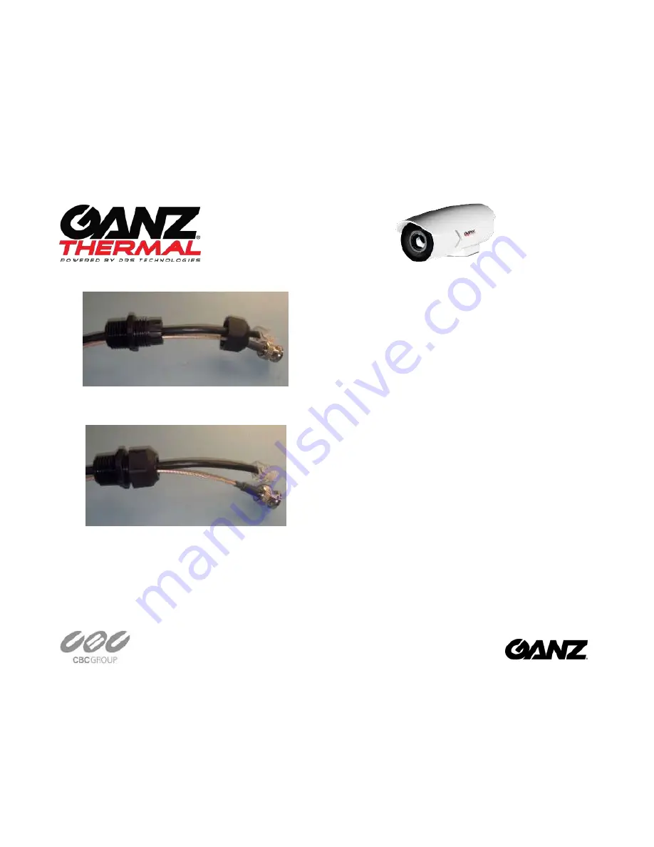
Tighten the gland nut onto the gland housing. Leave about 5 inches
of cable sticking out of the gland housing
5.
Insert the cable and gland into the camera. Connect the Analog
cable and CAT5 cable to the camera. Slide the gland housing-to-
chassis nut over the cables. Tighten the gland housing-to-chassis
nut into the camera
6.
Not shown, crimp the other end of the cables in place (not shown).
For all Configurations:
7.
Pull the cable(s) taut back through the IP Camera, exposing the
thread of the cable sealing gland out of the base of the IP Camera
8.
Assemble the Electrical Nut back onto the gland and tighten the
Nut securely until it is finger tight. Use a flat head screwdriver to
continue turning the electrical nut to approximately 50 in-lbs. of
torque
Assembling the Fixed Mount Camera
9.
Using 8 of the #6 screws, assemble the Base Mount adapter (or
newer hybrid mount), to the IP Camera. Tighten the 8 fasteners to
approximately 10 in-lbs. of torque with the Electric Screw Driver,
and T10 Security bit or Phillips #2 bit depending on screws
provided
10.
Using 4 of the #6 screws, assemble the optional Standard 4 hole
Mount, to the Base Mount, and tighten the fasteners to
approximately 10 in-lbs. of torque with the Electric Screw Driver,
and T10 Security bit or Phillips #2 bit depending on screws
provided.
11.
Connect the cable(s) to the respective connector:
a.
Ethernet: Ethernet Port
b.
Analog: Analog Video Out (Fixed Mount 320x240 &
640x480 Only)
c.
AC/DC Power for Fixed Mount 320x240 and 640x480:
Connect wires to power block according the pin-out
shown on the next page and described below:
i.
If powering the camera with an AC supply,
connect AC+ to the 24VAC input and the AC- to
the 12VDC input.
ii.
If powering the camera with a DC supply,
connect the DC+ to the 12VDC input and the
DC- (or ground) to the GND DC- (or ground) to
the GND input.


