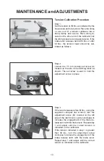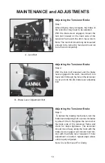
Step 2
Loosen the 1.5 mm locking set screw (A)
located on the side of the latching block as
shown. The set screw is used to hold the
adjustment screw in place.
A
13
MAINTENANCE and ADJUSTMENTS
Tension Calibration Procedure
Step 1
Set the tension to 60 lbs. as indicated by the
linear scale and rotary knob. Place the string
on one end of a tension calibrator into a
string clamp and secure. Place string lo-
cated on the other end of the calibrator into
the string tensioner and apply tension. If the
brake lever releases before 60 lbs. or after
60 lbs., the tension head should be cali-
brated as follows.
Step 3
If the lever releases before 60 lbs., using the
supplied L-shaped hex wrench, turn the
adjustment screw (B) located on the left
side of the latch block counter-clockwise to
increase the engagement of the brake re-
lease latch with the brake lever. Repeat step
1 and adjust until the correct tension is
indicated on the calibrator.
If the tension indicated in step 1 is greater
than 60 lbs., turn the adjustment screw
clockwise to reduce the engagement of the
brake release latch with the brake lever.
Repeat step 1 and adjust until the correct
tension is indicated on the calibrator.
B
B
A
Summary of Contents for X-Stringer
Page 17: ...16 NOTES...
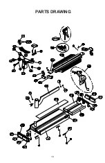
Page 19: ...18 PARTS DRAWING...


