background image


Flex 620


Installation  - Revision 5, 11/22/01


___________________________________________________________________________________________ 


49 


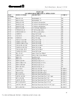
FLEX 600 

COMPATIBLE INDICATING APPLIANCES 

PART 
NUMBER 

MODEL NUMBER 

DESCRIPTION 

CURRENT  

70874 

MB-G6-24-R 

MOTORBELL 6" 

.030   

70875 

MB-G10-24-R 

MOTORBELL 10" 

.030   

71557 

RSP-2430-VFR 

30 Cd Strobe Adapter Red 

.124  

71631 

SRP-2475-VFR 

75 Cd Strobe Adapter Red, Sync. 

.215  

71558 

RSP-2475-VFR 

75 Cd Strobe Adapter Red  

.200 

71561 

SRP-24110-HFR 

110 Cd Strobe Adapter Red  

.250 

71586 

CSX10-24-DC-R 

10” SS Exp indoor Red.. 

.500 

71587 

CSXG10-24DC-R 

10” SS Exp outdoor Red.. 

.500 

71581 

CH-BF1-R 

Chime SS/Vib Red 

.020 

71585 

CH-CF1-W 

Chime SS/Vib ceiling white 

.020 

68460-01 

CH-DF1-R 

Chime Vibrating 

.020   

71583 

CH-CF1-LS-24-VFR 

Chime SS/Vib Red 

.100 

71300 

CH-DF1-LS-24-VFR 

Chime SS/Vib Red 

.100 

71301 

CH-DF1-LSM-24-VFR 

Chime SS/Vib Red 

.135 

71584 

CH-CF1-MS-24-CFW 

Chime SS/Vib White 

.155 

71302 

CH-DF1-MS-24-VFR 

Chime SS/Vib Red 

.155 

71582 

CH-CF1-IS-24-CFW 

Chime SS/Vib White 

.245 

71303 

CH-DF1-IS-24-VFR 

Chime SS/Vib Red 

.245 

71548 

SM-12/24-R 

Single Circuit Sync Module 

.025 

71549 

DSM-12/24-R 

Dual or Class A Sync Module 

.038 

70871 

MIZ-24-R 

Mini Horn Red 

.017  

70873 

MIZ-24-W 

Mini Horn White 

.017  

71287 

MIZ-24-LS-VFR 

Mini Horn/Strobe 15 Cd 

.092 

71288 

MIZ-24-LSM-VFR 

Mini Horn/Strobe 15/75 Cd 

.127 

71289 

MIZ-24-MS-VFR 

Mini Horn/Strobe 30 Cd 

.147 

71290 

MIZ-24-IS-VFR 

Mini Horn/Strobe 75 Cd  

.237 

71138 

MT-12/24-R 

Multi-tone Horn Red 

See DS851 

71573 

AMT-12/24-R 

Multi-tone Horn Red 3 Input 

See DS851 

71614 

MT4-12/24-R 

Multi-tone Horn Red Surface 

See DS851 

71292 

MT-24-LS-VFR 

Multi-tone Horn/Strobe Red  15 Cd 

See DS851 

71574 

AMT-24-LS-VFR 

Multi-tone Horn/Strobe Red 15 Cd 3 input 

See DS851 

71295 

MT-24-IS-VFR 

Multi-tone Horn/Strobe Red 75 Cd 

See DS851 

71575 

AMT-24-IS-VFR 

Multi-tone Horn/Strobe Red 75 Cd 3 input 

See DS851 

71293 

MT-24-LSM-VFR 

Multi-tone Horn/Strobe Red 15/75 Cd 

See DS851 

71576 

AMT-24-LSM-VFR 

Multi-tone Horn/Strobe Red 15/75 Cd 3 input 

See DS851  

71294 

MT-24-MS-VFR 

Multi-tone Horn/Strobe Red 30 Cd 

See DS851  

Technical Manuals Online! - http://www.tech-man.com

Summary of Contents for FLEXALARM 620

Page 1: ...NTIONAL FIRE ALARM CONTROL PANEL Installation Operation Manual The Gamewell Company P N 71217 60 Pleasant Street Revision 5 Ashland MA 01721 11 22 01 UL FM CSFM MEA Listed Technical Manuals Online htt...

Page 2: ...This page intentionally blank Technical Manuals Online http www tech man com...

Page 3: ...Gamewell Company Such information and technical drawings may not be copied or reproduced in any manner or disclosed to organizations that might be competitive to Gamewell without the express prior wri...

Page 4: ...This page intentionally blank Technical Manuals Online http www tech man com...

Page 5: ...rol panels to verify compatibility To maximize system performance and minimize risk of damage to the equipment we suggest using all Gamewell Components 4 There is no substitute for proper maintenance...

Page 6: ...This page intentionally blank Technical Manuals Online http www tech man com...

Page 7: ...Technical Manuals Online http www tech man com...

Page 8: ...This page intentionally blank Technical Manuals Online http www tech man com...

Page 9: ...Condition 17 default 17 Alarm Condition default 18 OPERATING PROCEDURES 19 INSTALLATION 24 Flex 620 System Housing 25 Hardware Assembly 26 Module Identification and Placement 28 Main Power Supply 30...

Page 10: ...rol By Event 59 Access Levels 60 Figure 4 1 Common Control Display Operating Mode 60 Password Entry 60 Input Circuit Programming 63 Output Circuit Programming 64 Restoring Output Circuits 65 Programmi...

Page 11: ...81 Change Dictionary 81 Change Dict Words 82 Upload Dictionary 82 Dictionary File 83 Change Card 84 Change Misc 84 Change Menu 1 85 Change Pass 85 Change Code 86 Change Date 87 Change Seq 87 Change B...

Page 12: ...Technical Manuals Online http www tech man com...

Page 13: ...This page intentionally blank Technical Manuals Online http www tech man com...

Page 14: ...Flex 620 System Description Revision 5 11 22 01 2 Section 1 FLEXALARM 620 System Description System Overview Technical Manuals Online http www tech man com...

Page 15: ...c system configuration in memory Then a control by event table is automatically created that allows any system input to activate the system outputs Upon completion of the initialization process the sy...

Page 16: ...ing functions and system memory as well as providing the local remote communications interface Relay Expansion Module The Relay Expansion Module REM provides 4 common relay circuits When connected to...

Page 17: ...ower left hand corner of the cabinet and connects via interconnecting cables to the bus driver module Lead Acid Battery Charger The lead acid battery charger module is provided with the main power sup...

Page 18: ..._________ Indicating Module Universal Signal Module The Flex 600 series universal signal modules USM 4 USM 8 are a multi function output modules available in either 4 or 8 circuit increments These mod...

Page 19: ...ol module is available in 4 or 8 circuit modules that are monitored and controlled by the MPU bus Their relays are rated at 10 Amps with supervised feedback points for positive confirmation of the pro...

Page 20: ...Technical Manuals Online http www tech man com...

Page 21: ...Section 2 FLEXALARM 620 System Operation Technical Manuals Online http www tech man com...

Page 22: ...gnal silence switch is alternating action switch Pressing the signal silence switch will return the silenced circuits to an active state Drill The Drill tactile switch DRILL will activate all circuits...

Page 23: ...tion When pulsing this indicates a problem with the incoming AC line voltage main or backup power supplies BATTERY FAULT The yellow Battery Fault LED indicates a problem with the battery or battery co...

Page 24: ...trouble has been acknowledged SIGNAL SILENCE The yellow Signal Silence LED indicates the audible signals connected to the system are not sounding SIGNAL SILENCE SOUNDING The yellow Signal Silence LED...

Page 25: ...bottom Relays 5 through 8 are fixed on the right side of the display top to bottom The display is complete with eight tactile switches eight red LED s and eight green LED s The eight point tactile swi...

Page 26: ...guished the system internal buzzer is silent all switches are inactive with the exception of the Enter button and all indicating devices are inactive __________________________________________________...

Page 27: ...ice s has been cleared and the momentary reset switch has been depressed If no further supervisory alarms exist in the system the panel will return to normal quiescent condition otherwise the panel wi...

Page 28: ...smoke detector go into alarm on the same AND circuit a second alarm output will occur This circuit is useful for a simple cross zone of two detectors An example of typical application would be in an e...

Page 29: ...y tie and common alarm relays activated ___________________________________________________________________________________________ Normal Quiescent Condition default When the system is in the normal...

Page 30: ...ts have been energized B If there are additional signal circuits in the system each circuit s red Alarm LED will be On steady to indicate that the circuit has been energized 5 Building Control Relay C...

Page 31: ...driver module display acknowledge ACK switch will stop pulsing and extinguish Any outputs programmed to return to the normal condition upon pressing the ACK switch will return to normal at this time...

Page 32: ...dition the momentary Reset switch should be depressed When the user presses the RESET switch the following actions will occur 1 All signal circuits will deactivate 2 All output relays circuits program...

Page 33: ...ng control circuit to Bypass will disable the circuit from activating E City Tie s bypassed Programming any City Tie circuit to Bypass will disable the circuit from the transmitting alarm WALKTEST Pro...

Page 34: ...Technical Manuals Online http www tech man com...

Page 35: ...This page intentionally blank Technical Manuals Online http www tech man com...

Page 36: ...m Operation Revision 5 11 22 01 _______________________________________________________________________________________________ 24 Section 3 FlexAlarm 620 Installation Technical Manuals Online http ww...

Page 37: ...ring terminals which the modules plug into are mounted directly to the backbox for ease of installation and servicing Modules can be removed for servicing without disturbing field wiring Systems are a...

Page 38: ...ing shipment Notify the manufacturer immediately if damage is detected Flex 620 Control Panel Mounting Complete the following instructions to mount the Flex 620 control panel The instructions are appl...

Page 39: ...initiating indicating building control module etc into alignment pins of cross rails 8 Connect the following interconnecting cables ribbon and power cables Reference drawing D W1142 all applicable wi...

Page 40: ...sent in the common control section operating display signal circuits city tie etc Cards 8 39 Card locations 8 through 39 are the optional modules installed in the cabinet bays see Figure I 1 Each modu...

Page 41: ...10 Ckt 33 40 jumper to 3 18 Ckt 41 48 jumper to 3 22 jumper to 3 15 jumper to 4 11 Ckt 49 56 jumper to 4 19 Ckt 57 64 jumper to 4 23 jumper to 4 FLEX 620 Expansion Cabinets w Bus Extender D I S P L A...

Page 42: ...pplicable refer to C W857 Aux Power Supply ___________________________________________________________________________________________ Specifications Input Voltage 120 VAC 50 60 Hz 3 amps Max Optional...

Page 43: ...ignation Description OUTPUT J1 connector RED 24VDC auxiliary power 4 amps available for signal circuits J1 connector BLK 24VDC auxiliary power 4 amps available for signal circuits J1 connector WHT Mon...

Page 44: ...21 VDC Common Smoke Detector Power 3 S 21 VDC 125mA resetable regulated power 4 second reset time 4 S 21 VDC common Security Power 5 12 12VDC 2 Amps regulated power 6 12 common for 12VDC City Tie 7 M1...

Page 45: ...ized A feedback circuit must have less than 50 ohms in loop resistance The function of relays K1 K4 Relay K1 Common Alarm Relay K2 Common Trouble Relay is normally energized Relay K3 Common Supervisor...

Page 46: ...or 220 VAC resistive fused 10 amps 8 2 M Trouble relay feedback point to monitor status of controlled device RELAY 3 COMMON SUPERVISORY Terminal Designation Description 9 3 NO Normally open Superviso...

Page 47: ...r module contains three jumpers for city tie programming J1 J2 J3 located in the center of the board These three jumpers are used to select the reverse polarity or the master box option for the city t...

Page 48: ...rd To install the U18 IC must be removed from its socket and replaced with the interconnecting cable from the Isolated RS 232 Card SW1 Default Settings S1 Open Do Not Change S2 Open Do Not Change S3 A...

Page 49: ...LED s and the internal sounder LED annunciation is also provided for AC power PreAlarm 2 signal circuits City Tie connection and Bypass Installation Diagram Refer to drawing D W1142 Wiring F620 Minim...

Page 50: ...rough S1 4 The I O circuit module uses the lower terminal block and connects via cables to the bus driver module The conventional input module and its display require one bay of the F620 system Note W...

Page 51: ...Initiating CCT 8 Class A Adapter Conventional Input Module Terminal Description Top Card 30869 CIM SDA Terminal Designation Description 1 1L1 Initiating CCT 1 Class A Return 2 1L2 Initiating CCT 1 Cl...

Page 52: ...osition each The SIGNAL I O board has an option that allows programming of the signal circuits to be operable under Default Alarm Mode A DIP switch S2 is provided on the module to select which signali...

Page 53: ...dicating CCT 8 output Class A Adapter Universal Signal Module Terminal Description Top Card 30940 USM SZA Terminal Designation Description 1 1AL1 Indicating CCT 1 output Class A return 2 1AL2 Indicati...

Page 54: ...lay Expander Module The relay expander provides the addition of four 4 supplementary form C 10 amp fused relay contacts The module also provides four 4 feedback input points switched negative using 3...

Page 55: ...15 4 C Form C common contact 10A 30VDC or 220VAC resistive fused 10A 16 4 M CCT 4 Relay feedback point to monitor status of controlled device Relay Expansion Module RM 4E 30874 Terminal Designator De...

Page 56: ...e slot in the Module bus Building Control Expander The building control expander module provides an additional eight 8 form A B jumper programmable 10 amp relays set up in four 4 ON relays and four 4...

Page 57: ...COM Common for CCT 4 relays terminals 13 15 15 4 OFF CCT 4 relay N C contact remove the W15 A Jumper 16 4 MON Monitor point for CCT 4 use 3 9K to when req BC 4E 30872 Terminal Designation Description...

Page 58: ...in the Module bus Display Module The display module provides eight 8 red circuit alarm LED s eight 8 yellow circuit trouble LED s Eight 8 circuit tactile switches are provided for programming and Byp...

Page 59: ...uring the power up sequence 6 System is at idle the normal quiescent condition The Power On is illuminated ___________________________________________________________________________________________ S...

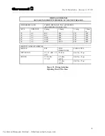
Page 60: ...4 STANDARD BASE SMOKE 70884 70885 70886 HD 3 25 70892 HB 13 STANDARD BASE W RELAY SMOKE 70884 70885 70886 HD 3 25 70893 STANDARD BASE HEAT DETECTOR 70887 70888 70889 70890 MAX AL CURRENT 100 MA 70894...

Page 61: ...71582 CH CF1 IS 24 CFW Chime SS Vib White 245 71303 CH DF1 IS 24 VFR Chime SS Vib Red 245 71548 SM 12 24 R Single Circuit Sync Module 025 71549 DSM 12 24 R Dual or Class A Sync Module 038 70871 MIZ 2...

Page 62: ...Strobe 15 Cd Sync 096 71569 RSP 241575 VFR Strobe 15 75 Cd Plate Mount 100 71554 SRP 241575 VFR Strobe 15 75 Cd Plate Mount Sync 138 71555 SR 241575 VFR Strobe 15 75 Cd Sync 138 71557 RSP 2430 VFR St...

Page 63: ...10 AWG OHM 1000 0 5amp 1 0amp 1 5amp 2 0am p 18 6 5 400 200 130 100 16 4 1 620 300 210 160 14 2 6 1000 500 330 250 12 1 6 1600 800 520 400 10 1 0 2500 1250 840 620 CIRCUIT CHARACTERISTICS CIRCUIT EOL...

Page 64: ...Technical Manuals Online http www tech man com...

Page 65: ...Section 4 FlexAlarm 620 Programming Technical Manuals Online http www tech man com...

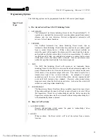
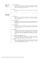
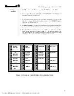
Page 66: ...rogramming mode Selecting Options 1 Each labeled key function switch on the CCD has an Upper and a Lower LED associated with it To choose a particular option press the tactile key switch which is asso...

Page 67: ...within the specified time limit the first alarm is ignored 3 AND The AND Fire Initiating Circuit will operate as an Automatic Alarm Initiating Circuit for the first two wire smoke detector alarm repo...

Page 68: ...cle C MARCHTIME 120 Marchtime 120 circuits when activated will provide a 24 VDC output on the selected circuits at a 120 pulses per minute rate with a duration of 50 on and 50 off cycle D TEMPORAL Tem...

Page 69: ...for steady or pulsing DC marchtime temporal etc and programmed separately 2 Signal Circuit types being selected on a USM Module are always allocated in circuit pairs an upper lower pair Each signal c...

Page 70: ...larm C Drillable Any signal circuit programmed as drillable will activate when the drill feature is activated Restoring Outputs A Restore On ACKNOWLEDGE Any active output point programmed to restore o...

Page 71: ...m level System Default activates ALL output signal circuits during a level 1 alarm C Relay Circuits Activation Any combination of relay circuit s may be assigned to activate from an input group When a...

Page 72: ...to programming Programming can only be completed using the level 4 password entry Default password for level 4 is 4444 When this mode is entered the key switches are redefined Reversing the front disp...

Page 73: ...d is entered This indicates that a new access level has been accepted B Password Required If a function is attempted from a level that does not allow access to that function i e Bypass from level 2 th...

Page 74: ...ption has been selected press the ENTER key The Password Required and Password Accepted LEDs will flash twice indicating that your selection has been accepted Note If a key that is not available for s...

Page 75: ...ble for input circuit types Automatic Verified And Supervisory Acknowledge Reset Signal Silence Drill B Once the desired circuit type LED is illuminated press the ENTER key to select the indicated cho...

Page 76: ...itch Note To deselect a circuit press the associated circuit switch until the LED is extinguished Any circuit deselected will default to a steady signal and all control by event information will be re...

Page 77: ...cuits LED s should be Lit in the default configuration then deselect the desired circuit s This will cause the LED to extinguish When the circuit LED is not lit for both the Signal Silence and Acknowl...

Page 78: ...t 1 From the programming mode select the Auto Silence option and press the ENTER key 2 Select all of the Signal Circuits that should automatically silence by pressing their associated circuit key 3 Af...

Page 79: ...by pressing the associated circuit key Once the desired group has been selected indicated by their associated LED s on press the ENTER key to confirm the selection Note If any previously programmed o...

Page 80: ...communication packages for computers will allow you to set the proper protocol for the communications port of your computer Procomm Software Configuration When using PROCOMM to communicate with your F...

Page 81: ...p From the ProComm SETUP MENU select option 4 to display the GENERAL SETUP menu The following settings should be displayed 1 Editor name 2 Default d l path 3 Default log file PROCOMM LOG 4 Screen dump...

Page 82: ...troubleshooting by providing detailed information of system faults Access Levels System access levels may be accessed via the computer By transmitting a Carriage Return Enter to the system you will be...

Page 83: ...Menu The System Menu menu is displayed when the programming password is entered System Menu 1 Display 2 Change 3 Test 0 Exit Display Menu Selecting the Display option from the System Menu allows the...

Page 84: ...rd 1 ID 12 is CCM1 LEDs T Switches Card 2 ID FF is Vacant Card 3 ID FF is Vacant Card 4 ID 01 is CCM4 2 Sig Ckt Class A Card 5 ID 02 is CCM5 4 Rel Ckt Card 6 ID 05 is CCM6 Misc Ckts Card 7 ID 07 is CC...

Page 85: ...9 Card numbered 8 through 39 are individual modules physically installed in cabinet bays 4 8 bay cabinets and 4 8 bay expander cabinets see Installation Section 3 Figure 3 1 for cabinet layout Each mo...

Page 86: ...w no tactile sw Left Control Display 16 Combo Red Green Yellow LEDs no 3 pos sw tactile sw installed Left Control Display 13 Combo Red Yellow LEDs no 3 pos sw no tactile sw Right Control Display 12 Co...

Page 87: ...ftware packages follow the procedure required for that software to receive an ASCII file The next CR the system receives will start the transmission of the file Configuration Menu 1 Display 2 Download...

Page 88: ...smit the complete set of 5 dictionaries to the RS 232 port When this is selected the system prompts the user to perform several steps These steps are the actions required to receive an ASCII file when...

Page 89: ...ding the system status changes for the previous 1000 events or since the last time the system Smart Start feature was invoked Display Menu 1 Config 2 Dict 3 Events 4 Misc 0 Exit 3 Start of Event Buffe...

Page 90: ...Display Menu 1 Config 2 Dict 3 Event 4 Misc 0 Exit 4 Display Menu Misc 1 Pass 2 Codes 3 Ver 4 Zone 0 Exit 1 1 Pass 1111 User ID USER1 Sec 1 2 Pass 2222 User ID USER2 Sec 2 3 Pass 3333 User ID USER3 S...

Page 91: ...3456 35 123456 36 123456 37 123456 38 123456 39 123456 40 123456 41 123456 42 123456 43 123456 44 123456 45 123456 46 123456 47 123456 48 123456 49 123456 50 123456 51 123456 52 123456 53 123456 54 12...

Page 92: ...one cards installed in the system The card ID and description is displayed along with each associated circuit type and assigned code information Display Menu Misc 1 Pass 2 Codes 3 Ver 4 Zone 0 Exit 4...

Page 93: ...he PROCOMM software package to Upload an ASCII file When using other software packages the keystrokes required to Upload an ASCII file should be followed When using the PROCOMM software package the fo...

Page 94: ...ry a file containing the new dictionary entries must be created using an ASCII text editor The SAN RAN disk P N XXXXX contains the AHED text editor that may be used to create the dictionary file The d...

Page 95: ...throughout the five dictionaries The end of dictionary five is also signified by two fore slashes Some important points to keep in mind when writing the file are as follows Dictionary one through dict...

Page 96: ...ll ensure that the control by event table is Change Menu 1 Config 2 Dict 3 Card 4 Misc 0 Exit 3 Change Card Menu 1 Add 2 Delete 0 Exit 1 Enter Card To Add Delete Existing Card First Press Enter Key To...

Page 97: ...ssigned to that password is defined NOTE Before changing the password 4 programming password make sure that you have added a new password to access the programming Sec 4 area Change Menu Misc 1 Menu1...

Page 98: ...ou to change the Timing the number of Cycles and the output of the signal circuits after the code is complete silence or March Time signal Change Menu 1 1 Pass 2 Code 3 Date 4 Seq 5 Baud 6 Words 0 Exi...

Page 99: ...tion allows the user to redefine the access levels associated with each of the sequence keys Each of these keys is assigned an access level by default The Acknowledge key is assigned to level 1 access...

Page 100: ...nopqrstuvwxyz 0123456789 ABCDEFGHIJKLMNOPQRSTUV WXYZ _ abcdefghijklmnopqrstuvwxyz 0123456789 ABCDEFGHIJKLMNOPQRSTUVWXYZ _ abcdefghijklmnopqr stuvwxyz 0123456789 ABCDEFGHIJKLMNOP QRSTUVWXYZ _ abcdefghi...

Page 101: ...5 Baud 6 Words 0 Exit 6 Press an I O Ckt or Enter Ckt 01 Press an I O Ckt or Enter Ckt 49 Enter Ckt s Word To Change 1 5 1 Current Word Enter Replacement Word 0 127 1 Fire Alarm Enter Ckt s Word To Ch...

Page 102: ...y until a2 is displayed a3 should be displayed if the third letter is desired and should be displayed if the number associated with that key is desired 1 2 The case of the letters may be changed by pr...

Page 103: ...u Misc 1 Menu1 2 Menu2 0 Exit Change Menu 2 1 City 2 Sig Sil 3 Ann 4 Trbl 5 Dialer 6 Prefix 0 Exit 1 Press Enter Key To Exit Press Any Other Key To Toggle City Tie Is In Standard Mode City Tie Is In C...

Page 104: ...Installed is selected Normal reporting of AC failure troubles is restored when the Dialer Is Not Installed option is selected Change Menu 2 1 City 2 Sig Sil 3 Ann 4 Trbl 5 Dialer 6 Prefix 0 Exit 5 Pre...

Page 105: ...put of the card location number see installation section for card location numbers to be tested The card is continuously scanned and a real time value in Hexadecimal format base 16 is returned for eac...

Page 106: ...te when the display switch is pressed NOTE When card 0 main display is selected on the 630 and 650 systems no input card option is displayed Pressing the front panel switches will toggle the LED s and...

Page 107: ...wo measurements must be greater than 142 but less than 255 for a reading of Good Note The values displayed are derived from an A D conversion and not displayed in actual voltages Test Menu 1 Input 2 O...

Page 108: ...feedback point and 006 for each active Normal 022 per active circuit BC 8 010 003 for each inactive feedback point and 006 for each active Normal 022 per active circuit CABINET EXPANDER 001 001 ALARM...

Reviews: