G
AMATRONIC
E
LECTRONIC
I
NDUSTRIES
L
TD
.
CENTRIC User Guide, rel. 3.4
25
When all modules are operating normally, the redundant modules participate in the load sharing.)
A redundant module is one in excess of the minimum number of modules required to meet the UPS’s
maximum expected load. If any module fails, the presence of the “extra” or redundant module(s)
guarantees that the maximum expected load can still be supported. The number of redundant modules can
be zero or greater, depending on the maximum expected load and the number of available module shelves.
When all modules are operating normally, the redundant modules share the load equally with the rest of the
modules.
Defining a redundancy of one or more modules affects the UPS’s perception of its maximum output
capability. The redundant module(s) is not taken into account in calculating the UPS’s maximum output
capability.
As an example, say we have a UPS system with eight module shelves that can hold modules of 25 kW.
The maximum expected load is 155 kW. Seven modules (175 kW) are required to supply the maximum
expected load. An eighth module can be installed and a redundancy of one module declared, giving the
UPS a total capacity of 200 kW. If any one of the five modules fails, the UPS will still be able to supply
power for the maximum expected load.
If all of the modules are operating normally, and the load unexpectedly increases to 160 kW, the system will
indicated an overload condition, because the redundant module is not taken into account in calculating the
UPS’s maximum output capability.
Redundancy is not a property of any particular module. Redundancy is simply the presence of one or more
modules in excess of the number of modules required to meet the maximum expected load.
Note: When modules are added to the system or removed from the system, the value of total number of
modules must be adjusted. You may or may not at that time also want to change the number of redundant
modules.
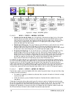
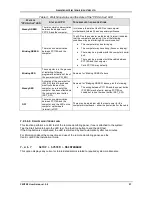
7.2.1.3
SETUP > SYSTEM > NUMBER OF BATTERIES
Specify the number of battery strings connected to the UPS. You can specify 1, 2, or 3 battery strings. The
Centric
requires you to enter a password to change this setting.
(Note: A “battery string” or “battery set” is the basic number of batteries required to provide standard
backup capabilities. For the Centric, this is 60 x 12 V batteries. A battery string may be housed in one or
more battery cabinets. For extended backup time, multiple battery sets can be attached to the Centric.)
7.2.1.4
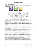
SETUP > SYSTEM > SYSTEM TYPE
Model type:
Indicate the maximum output power of your system. Here, assume no redundant modules, so
that all modules are considered when calculating the maximum potential system output..
Multi-system mode:
Indicate that the UPS will be operating in parallel configuration (multi-system mode).
A password may be required to modify this setting. If you do not have the appropriate password,
contact your distributor or sales agent.
7.2.1.5
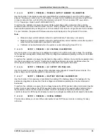
SETUP > SYSTEM > SHUTDOWN AND AUTORESTART
Use this option to specify the behavior of the UPS during a failure of the ac mains power.
•
You can set a specific limit to the duration of battery mode, after which time the UPS will
automatically turn itself off.
•
You can instruct the UPS to continue to supply backup power until the battery voltage descends to
the predefined level at which the UPS will turn itself off.
In this screen, you also specify if the UPS should automatically turn itself back on when the ac mains power
returns following a power failure, or if it should remain off.


