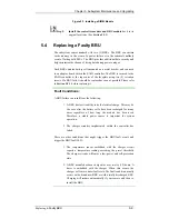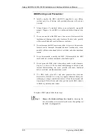
Galaxy GHDXS2-1430R-16F4D Installation and Hardware Reference Manual
5-6
Replacing
Controller Module Components
Step 3.
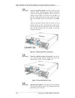
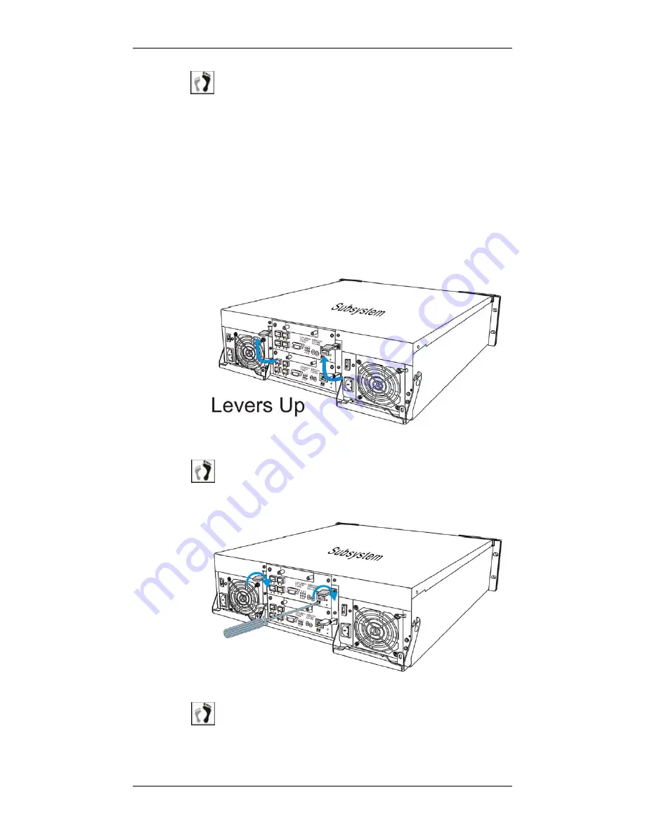
Secure the controller module.
Carefully push the controller
until you feel the contact resistance when the board edge
connectors are engaging the backplane. Do not use force. If
unusual contact resistance is felt, remove the controller, wait
for a few seconds and try again. Use the ejection levers on the
sides of the controller to secure it into the chassis. (See
Figure
5-4
)
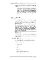
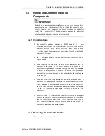
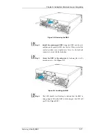
When the controller is inserted with the levers at its lowest
position, notches on the levers should properly clinch to the
round metal protrusions on the interior walls of the module
bay. You may then pull the lever upward to secure the
controller into chassis.
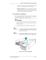
Figure 5-4: Lifting the Ejection Levers Upward
Step 4.
Secure the controller module to the chassis.
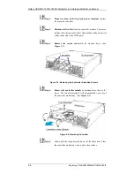
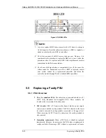
Fasten the two
(2) screws previously removed through the screw holes
underneath the ejection levers. (See
Figure 5-5
)
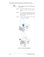
Figure 5-5: Securing Retention Screws
Step 6.
Re-attach all the cables
that were removed. These include the
host link cables, Ethernet cable to the management port, and
serial cables to the COM ports.

