background image

9

8

A

B

C

D

7

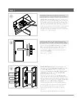
•  Fold 

template

 where indicated (make sure the correct 

template is used).

• 

Position template

 on door edge with the template on the 

INSIDE door face

. Close the door while holding template  

to door face. 

Line up the


latch centreline

 on the template 

with the 

MIDDLE of the strike

 on the door frame.

•  Firmly hold template and mark on door face the 

hole centre 

points.

 Without moving the template, open the door and 

mark latch height

 and 

Battery Box height

 on door edge.

•  Remove template and 

measure door thickness.

 Divide this 

size in half and mark centre of door on Battery Box height 
and latch height markings.

A

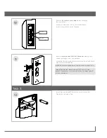
   •  Drill 1 inch hole 

85mm

 deep in 

3 places on door edge.


    •  Chisel wood to join the 

2 Battery Box holes.

B

   •  Drill 

10mm door face holes in 7 places,

 drilling from  

both sides of the door.

C

   •  Drill 

pilot holes

 for 

larger holes in 3 places

 (suggested 

size 3mm), drilling from both side of the door.

    • 

Enlarge

 the 

3 pilot holes to 54mm,

 drilling from both 

sides of the door.

D

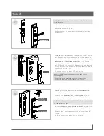
   •  Mark and chisel a 

recess of 4mm

 for the 

Battery Box 

faceplate.

 (So that Battery Box faceplate is flush with 

the door edge). Use the Battery Box as a template.

    •  Mark and chisel a 

recess of 4mm

 for the 

latch faceplate. 


(So that the latch faceplate is flush with frame the door 
edge). Use the latch as a template.

• 

Insert the latch

 making sure that the tapered (bevelled)  

side of the latch faces towards the door frame when the 
door is open.

•  Fix using 2 wood screws from 

KIT A.

• 

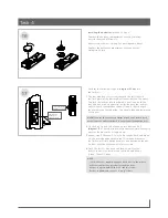
Insert the Battery Box.


The wires exiting the Battery Box should face towards  
the outside of the door. Wrap the wires over the top of the 
Battery Box and pass the connector through the top hole  
on the inside door face. (The wires will now be coming 
through to the inside). 

See Step 11.

•  Fix using 2 black wood screws from 

KIT D.


Task 2

1/2 door  
thickness

1/2 door  
thickness

Battery Box  

height marking

Latch height 

marking

Template in 

middle of Strike

Strike


NOTE: It is important to drill holes squarely.

NOTE: Do not over tighten these screws. Do not use power tools.

CaUTION: The door drilling templates are different for the  
G+ Volt and the G+ apex style locksets.
Please ensure that the correct template is used. The template  
is clearly marked “VOLT” or “aPEX”.

Summary of Contents for G+ LOCKSET

Page 1: ...ery and Electric Locksets G ACCESS SYSTEM 54mm 10mm 10mm 10mm 10mm 10mm 10mm 10mm 54mm 54mm BACKSET 60MM BACKSET 60MM FIT HERE ON DOOR EDGE G ACCESS SYSTEM Lever height Strike height Power Transfer Unit height G LOCKSET ELECTRIC Installation Template for Door Frame G LOCKSET ELECTRIC Installation Template for Door Frame 75mm Please refer to G Lockset Installation Manual for Instructions on how to ...

Page 2: ...ight mark you made in the previous step Firmly hold the template and mark the 2 Power Transfer Unit heights top markings and the 2 Strike heights bottom markings on the frame Remove the template and measure the door thickness Divide this size in half and measure this size from the jam Take note of any weather strips that may be fitted to the door jam Mark this position on the 2 Power Transfer Unit...

Page 3: ... from the In line Power Unit This will be in the door frame cavity Pull the end of the wire out through the top hole in the door frame Connect the Power Transfer Unit to the wire from the In line Power Unit Insert the Power Transfer Unit into the door frame As you do this carefully guide the excess wire back into the door frame cavity Fix using 2 black wood screws from KIT D Insert the strike and ...

Page 4: ...ecess of 4mm for the Battery Box faceplate So that Battery Box faceplate is flush with the door edge Use the Battery Box as a template Mark and chisel a recess of 4mm for the latch faceplate So that the latch faceplate is flush with frame the door edge Use the latch as a template Insert the latch making sure that the tapered bevelled side of the latch faces towards the door frame when the door is ...

Page 5: ... Assemble the Battery Box transmitter and fix using 2 black wood screws from KIT D 10 11 NOTE Do not over tighten these screws Do not use power tools IMPORTANT NOTICE NiMH batteries MUST be used in this product Failure to do so could result in severe damage and will void any warranties Switch A Shift selection Switch B Revert to privacy 12 Install 6 posts from KIT B onto the outside faceplate Tigh...

Page 6: ...wise Leave key in this position Assemble the connector from the Battery Box with the connector on the faceplate Make sure they are firmly pressed together Hold the faceplate flush against the door face making sure that wires from the Battery Box are not trapped The key can now be turned back to the vertical position and removed The faceplate is now temporarily secured and will not fall if let go F...

Page 7: ...first G Key to be taught press buttons 4 5 diagram 17 These buttons must be pressed simultaneously until the lockset emits a single beep 3 Repeat step 2 for each G Key to be taught Each additional G Key must be added within the 10 seconds otherwise the lockset will time out and replace any previously taught G Keys with the keys taught in this session 4 Once the last G Key has been taught wait for ...

Page 8: ...aranteed and Gainsborough Hardware reserves the right to alter amend or delete any part of this document without prior notice This disclaimer is subject to any contrary legislative provisions Take care electricity kills Switches power outlets and other fixed wire products must be installed by a licensed electrical contractor or similarly qualified person Gainsborough Hardware Industries Limited Ho...

Reviews: