22
4-3
Hot Water System
4-3.1 Unvented Hot Water Cylinder
The cylinder may be installed at any convenient above ground location within the
dwelling. As Electrastream is a sealed system, the cylinder is equally effective on any
floor.
The cylinder must always be installed vertically.
Avoid positioning the cylinder where it may be subjected to frost.
The floor must give adequate support to the filled cylinder.
Cylinders with legs are supplied with self-tapping screws for floor fixing.
For maintenance purposes leave at least 500mm at the front of the cylinder.
The cylinder must be fitted with a drain valve, this should be as low as possible and able
to drain at least 80% of the cylinder’s volume.
The cylinder may be installed below ground i.e. in a basement, providing that the
expansion relief discharge pipe is plumbed to a metal receptacle with a suitable pump
and switch arrangement, current Building Regulations give details of this. An alternative
is to use a Hepworth HepvO Self Sealing Waste Valve, this must be installed to the
manufacturers specification and building regulations.
4-3.2 Cylinder Thermostat Box
The cylinder thermostat is an integral part of the Electrastream Control, a sensor and lead
is provided. The sensor must be inserted into the phial of the cylinder thermostat box
and the lead wired back to the’Temp Sensor’ terminals of the Electrastream Control.
A thermal cut-out thermostat is fitted in the cylinder thermostat box, this should be wired
back to the ’O-T’ terminals of the Electrastream Control.
The cylinder thermostat box must be fitted to the cylinder with its phial inserted into the
socket provided in the cylinder. A screw is provided to clamp the unit in place.
4-3.3 Combination Valve
The Combination Valve is supplied separate, it has to be fitted to the pipework suppling
the cylinder.
For standard configurations see 1-2.
The valve has an integral 3.5 Bar Pressure Reducing Valve and a 6 Bar Expansion Relief
Valve. It also has a line strainer, this should be checked as part of routine inspection.
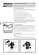
22mm SUPPLY
FROM MAINS
15mm TO TUNDISH
EXPANSION RELIEF
Set at 6 Bar
22mm SUPPLY TO CYLINDER AND
ELECTRASTREAM ACCUMULATOR
Fig. 4-3b Combination Valve
3.5 Bar PRESSURE
REDUCING VALVE
Fig. 4-3c Expansion Vessel Connection
¾ BSP PORT FOR
EXPANSION VESSEL
LINE STRAINER
INST
INST
INST
INST
INSTALLA
ALLA
ALLA
ALLA
ALLATION 4
TION 4
TION 4
TION 4
TION 4
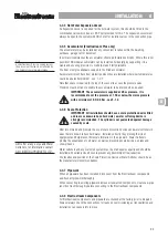
Fig. 4-3a Cylinder Thermostat Box
Note
For wiring see Fig. 3-3a
44444
Summary of Contents for Electrastream
Page 40: ...39 Notes ...


