background image

14

Note
For more information see 4-5.

It is recommended the system is inspected by an approved engineer once per year.
The service procedure is included in section 6.

2-6

Servicing

OPERA

OPERA

OPERA

OPERA

OPERATOR CONTROLS      2

TOR CONTROLS      2

TOR CONTROLS      2

TOR CONTROLS      2

TOR CONTROLS      2

it is caused by the heating system or hot water system and do the following:-
1.

Turn ON a hot tap to relieve the pressure.

2.

Turn OFF the immersion heater.

3.

Turn OFF the heating system.

4.

Investigate possible cause for high pressure from the hot water system e.g:-
i

Cylinder Thermostat is set too high.

ii

Restriction in hot water pipework.

iii

Loss of air pressure in the accumulator resulting in no expansion
(Electrastream Plus only)

If the heating heating system is the cause then :-
5.

Check that the radiators are turned on, the heating system should never be operated
with all radiators OFF.
If all radiators are fitted with thermostatic valves, these can all be in a shut condition
if the temperature in the dwelling is sufficient.  In this circumstance the heating
system should have a bypass that should be open - see fig. 1-2a & 1-2b.

6.

Investigate possible cause for high pressure e.g. air in the heating system.

7.

Contact the installer before restarting the system.

2-5

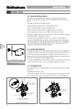
Thermostatic Mixing Valve

The Mixing Valve will be fitted in the supply to the hot taps/outlets, it may be in a different
location than the cylinder.  This valve mixes hot water from the cylinder with cold water to
provide hot water of a constant temperature at the taps.
The recommended maximum hot water temperature at the taps is 60ºC.
The recommended setting of the valve is between No.4 and 6 (49º to 58ºC).
The Mixing Valve is factory set to the following approximate mixed outlet temperatures:-

 Knob Position

Min

1

2

3

4

5

6

7

Max

 Output Temp. ºC

27º

32º

38º

44º

49º

53º

58º

63º

67º

Fig. 2-5a  Thermostatic Mixing Valve

WARNING
Do not set the water temperature too high as this can cause scalding
especially to the young and old.

22222

Summary of Contents for Electrastream

Page 1: ...fices Home Offices and Granny Annexes Plus Plus Plus Plus Plus Electrastr Electrastr Electrastr Electrastr Electrastream Plus eam Plus eam Plus eam Plus eam Plus Electrastr Electrastr Electrastr Electrastr Electrastream eam eam eam eam Patents GB23449908 Application 01514800 2 WRC Approval Pending USER and INSTALLATION INSTRUCTIONS 05 12 06 30 000 9kW for Heating and Hot Water ...

Page 2: ...ION Section 2 Operator Contr Section 2 Operator Contr Section 2 Operator Contr Section 2 Operator Contr Section 2 Operator Controls ols ols ols ols 2 1 System Control 7 2 2 Electrastream Control Unit 9 2 3 Shut Off Valves 12 2 4 Expansion Relief Discharge 13 2 5 Thermostatic Mixing Valve 14 2 6 Servicing 14 Section 3 T Section 3 T Section 3 T Section 3 T Section 3 Technical Information echnical In...

Page 3: ... powered titanium electric immersion heater Hot water is drawn from the cylinder and mixed with cold water by a thermostatic mixing valve this ensures safer lower temperatures at the hot water outlets The hot water within the unvented indirect cylinder also heats the water for the heating system via the indirect coil within the cylinder The circulating pump for the heating system is controlled by ...

Page 4: ...e within the dwelling no header tank 12 Low maintenance cost no CORGI Landlord Certificate required 13 9kW titanium immersion heater combined 3 x 3kW 14 Immersion heater will still work should one or two of its elements fail 15 Stainless Steel Unvented Cylinder with 20 years guarantee ELECTRASTREAM PLUS 1 Balanced hot and cold supply to taps 2 All taps and showers at maximum system pressure 3 Pres...

Page 5: ...N 1 INTRODUCTION 1 INTRODUCTION 1 INTRODUCTION 1 INTRODUCTION 1 1 2 System Layout Fig 1 2a Typical Schematic Installation Electrastream Fig 1 2b Typical Schematic Installation Electrastream Plus PARTS SUPPLIED PARTS SUPPLIED ...

Page 6: ...nation valve Once passed the valve it supplies the accumulator and the hot water cylinder Supply to the cold outlets is taken from a Tee fitting at the base of the accumulator 1 2 2 System Control The system is controlled by a purpose designed Electrastream Control unit this controls the hot water and heating ON OFF times together with the heating pump and valve The control also has a dedicated pr...

Page 7: ...be installed within the dwelling or loft space without further protection Cylinders or accumulators must have frost protection when they are installed where low temperatures could be a potential problem Cylinders can be protected by a frost thermostat To comply with Building Regulations all necessary pipework must be suitably lagged 1 2 8 Handling and Storage The Electrastream system will be deliv...

Page 8: ...ater WARNING The immersion heater does not have an internal thermostat like most immersion heaters the cover should not be removed When the cover is removed live electrical terminals are exposed ISOLATE THE IMMERSION HEATER BEFORE REMOVING ITS COVER 2 1 3 Thermal Cut Out Thermostat In the thermostat box on the cylinder is the thermal cut out thermostat This prevents the water within the cylinder f...

Page 9: ...n 2 1 5 Pump The heating circulating pump is controlled by the Electrastream Control unit in response to the room thermostat The pump has 3 speeds it is normally set to speed 2 Display icon Pump indicates the pump is ON 2 1 6 Room Thermostat The room thermostat controls the heat within the dwelling When the room thermostat is calling for heat and the Electrastream Control is set for heat ON the he...

Page 10: ...Unit Fig 2 2a Electrastream Control Unit Normal Screen 2 2 1 Control Unit Display Normal Screen HEAT 1 Indicates Element 1 is ON HEAT 2 Indicates Element 2 is ON HEAT 3 Indicates Element 3 is ON VALVE Indicates Heating Valve is OPEN PUMP Indicates Heating Pump is ON THERM Indicates Room Stat is calling for heat Heating on 2 2 2 2 2 ...

Page 11: ...een NORMAL SCREEN 2 2 2 Display Time Settings Display only Indicates the total hours that each immersion heater element has been in operation For service engineers information only Fig 2 2b Electrastream Control Unit Time Setting Displays Notes All times are given in 24 hour clock OPERA OPERA OPERA OPERA OPERATOR CONTROLS 2 TOR CONTROLS 2 TOR CONTROLS 2 TOR CONTROLS 2 TOR CONTROLS 2 2 2 2 2 2 ...

Page 12: ...lectrical supply to enable Electrastream to be used during both off peak and normal tariffs consult the installing electrician OPERA OPERA OPERA OPERA OPERATOR CONTROLS 2 TOR CONTROLS 2 TOR CONTROLS 2 TOR CONTROLS 2 TOR CONTROLS 2 2 2 2 2 2 Start 1 03 00 3am Stop 1 05 00 5am Start 2 14 00 2pm Stop 2 16 00 4pm Start 3 20 00 8pm Stop 3 21 30 9 30pm All times fall within Economy Tariff Boost can be u...

Page 13: ... Shut Off Valves The Electrastream installation will have a number of shut off valves the location of these will be dependent on the installation figs 2 3a and 2 3b show typical layouts Fig 2 3a Typical Shut Off Valve Locations Electrastream Fig 2 3b Typical Shut Off Valve Locations Electrastream Plus 2 2 2 2 2 ...

Page 14: ... In the event of water steam being seen at the discharge pipe or Tundish ascertain whether Fig 2 4a Tundish Note The Tundish or discharge pipe should remain visible do not box in or cover up AIR BREAK DISCHARGE PIPE 2 4 Expansion Relief Discharge 2 3 1 Stop Cock Normally located at the point where the mains supply enters the dwelling Shuts off the mains water supply to the dwelling 2 3 2 Double Ch...

Page 15: ...re fitted with thermostatic valves these can all be in a shut condition if the temperature in the dwelling is sufficient In this circumstance the heating system should have a bypass that should be open see fig 1 2a 1 2b 6 Investigate possible cause for high pressure e g air in the heating system 7 Contact the installer before restarting the system 2 5 Thermostatic Mixing Valve The Mixing Valve wil...

Page 16: ...and plastic Push fit fitting must be specified as suitable for sealed systems 3 1 4 Electrics m a e r t s a r t c e l E y l p p u S e s a h P e l g n i S V 0 4 2 e s u F p m a 5 4 e z i S e l b a C y l p p u S m m x e r o c 3 m m r e d n i l y C t c e r i d n I 5 2 1 I D T 0 5 1 I D T e p y T r e t a e H n o i s r e m m I t n e m e l E m u i n a t i T r r o c 6 9 3 7 2 5 3 3 0 6 N E 1 A 5 1 A 1 1 ...

Page 17: ...a Cylinder Dimensions r e d n i l y C l e d o M S N O I S N E M I D y t i c a p a C A B Ø C D E 5 2 1 I D T s e r t i l 5 2 1 5 4 0 1 5 0 5 5 1 3 5 7 6 5 0 8 0 5 1 I D T s e r t i l 0 5 1 5 0 2 1 5 0 5 5 1 3 5 1 8 5 6 9 r e d n i l y C l e d o M y t i c a p a C e c a f r u S l i o C l i o C g n i t a R t h g i e W y t p m E t h g i e W l l u F 5 2 1 I D T s e r t i l 5 2 1 m 5 7 0 W k 5 0 2 g k 3 ...

Page 18: ...INGS ARE SUPPLIED TO ADAPT THE CYLINDER TAPPINGS TO THE PIPE SIZES SHOWN Fig 3 2b Twin Cylinder Dimensions r e d n i l y C l e d o M S N O I S N E M I D A B Ø C D E F G 0 1 2 I S T I 5 7 4 1 5 0 5 6 0 8 6 0 2 1 0 2 2 1 5 2 2 5 2 6 0 0 3 I S T I 0 9 7 1 0 6 5 6 1 1 1 6 1 5 1 6 5 5 1 0 6 2 0 0 8 45 22 5 ØB A E G F HOT WATER TO TAPS 22mm COLD MAINS SUPPLY IN 22mm PRIMARY HEAT SOUCE FLOW SOLAR BOILER ...

Page 19: ...28 COMPRESSION FITTING COMPRESSION FITTINGS 1040 100 Essential Access 3 2 3 Accumulator Dimensions Water content is up to 65 of the accumulator volume Total weight weight empty water content 1kg litre Fig 3 2c Accumulator Dimensions r o t a l u m u c c A l e d o M e z i S y t i c a p a C s s o r G t n e t n o C r e t a W y t p m E t h g i e W 0 0 2 0 7 1 s e r t i l 0 1 1 o t p u g k 4 0 3 TECHNIC...

Page 20: ...19 3 2 5 Cased System Dimensions Fig 3 2e Cylinder Dimensions PIPEWORK NOT TO SCALE 3 3 3 3 3 A A A A ATION 3 TION 3 TION 3 TION 3 TION 3 ...

Page 21: ...rey FLOW FROM BOILER g y L2 HONEYWELL V4043H Normally Closed L1 L2 N E N L E N L E T STAT PUMP VALVE 16 AMP FUSE 16 AMP FUSE 16 AMP FUSE 5 AMP FUSE N L E MAINS IN 230V AC N L E H1 N L E N L E H1 H1 black blue brown g y blue brown g y blue brown g y blue brown g y blue brown g y black blue brown g y blue brown g y blue brown g y blue brown g y CONTROL BOX TERMINAL blue brown g y blue brown g y Note...

Page 22: ...ent IEE Wiring Regulations egulations egulations egulations egulations All electrical work must comply with any r All electrical work must comply with any r All electrical work must comply with any r All electrical work must comply with any r All electrical work must comply with any relevant r elevant r elevant r elevant r elevant regulations that apply at the time of egulations that apply at the ...

Page 23: ...nder thermostat is an integral part of the Electrastream Control a sensor and lead is provided The sensor must be inserted into the phial of the cylinder thermostat box and the lead wired back to the Temp Sensor terminals of the Electrastream Control A thermal cut out thermostat is fitted in the cylinder thermostat box this should be wired back to the O T terminals of the Electrastream Control The...

Page 24: ...s strongly recommended The cylinder is not guaranteed against damage caused by scale GAH recommend and promote the use of scale prevention devices and water softeners in areas that are known to have hard water Installed correctly they prolong the life of equipment and help prevent limescale formation in the pipework Water Softeners provide the advantages of soft water as well as preventing scale b...

Page 25: ...e valve Notes Refer to the mixing valve manufacturer s instructions supplied with the valve for further information Put these with this manual The mixing valve is not guaranteed against corrosion or blockage caused by excessive scale M I X C0LD HOT Fig 4 3d Thermostatic Mixing Valve MIX CONNECTED TO DRAW OFF TAPS HOT OR COLD AS MARKED CHECK VALVE CHECK VALVE SERVICE VALVE SERVICE VALVE SERVICE VAL...

Page 26: ... must be piped using 15mm copper pipe to a visible position outside the dwelling The pipe must have a continuous fall and ideally be terminated over a drain Local by laws may require a Tundish to be fitted see note The heating TPR valve may be plumbed to the hot water system discharge prior to the Tundish see 4 5 IMPORTANT Scalding water and steam can be emitted from the discharge pipe Position th...

Page 27: ... 4 4 9 Bypass An automatic bypass valve should be fitted between the flow and return of the heating system normally after the pump but before any radiator take offs The valve must be set to suit the pressure of the system 4 4 7 Filling Loop A Filling Loop comprising a flexible hose double check valve and an isolating valve is supplied for filling and topping up the system The filling loop should b...

Page 28: ...ully 2 Downward discharges at a low level i e up to 100mm above external surfaces such as car parks hard standings grassed areas etc These are acceptable providing that where children may play or otherwise come into contact with discharges a wire cage or similar guard is positioned to prevent contact whilst maintaining visibility 3 Discharges at high level i e into a metal hopper and metal downpip...

Page 29: ...m m 5 3 m m 2 4 m 9 o t p u m 8 1 o t p u m 7 2 o t p u m 0 1 m 4 1 m 7 1 1 G m m 8 2 m m 5 3 m m 2 4 m m 4 5 m 9 o t p u m 8 1 o t p u m 7 2 o t p u m 4 1 m 7 1 m 3 2 4 5 5 Worked Example G temperature and pressure relief valve TPRV with a discharge pipe D2 having four elbows and length of 7m from the tundish to the point of discharge From Table 1 Maximum resistance allowed for a straight length ...

Page 30: ...tandard systems with normal mains pressure however if the mains pressure is more or fluctuates above 4 Bar a Mains Pressure Reducing Valve should be considered 2 The Combination Valve has an integral pressure reducing valve fixed at 3 5 Bar therefore the System Pressure will be 3 5 Bar maximum 3 If the Mains Pressure is less than 3 5 Bar then the System Pressure will be at maximum Mains Pressure 4...

Page 31: ...V l l e w y e n o H m e t I t r a P y t Q s e t o N 1 l o r t n o C m a e r t s a r t c e l E 1 r o s n e s e r u t a r e p m e t r e d n i l y c w C 2 r e d n i l y C d e t n e v n U 1 0 5 1 I D T r o 5 2 1 I D T 3 r e t a e H n o i s r e m m I W k 9 1 m u i n a t i T W k 3 x 3 d e n i b m o C 4 p m u P g n i t a l u c r i C H A G 1 e s a h P e l g n i S V 0 4 2 5 s e v l a V g n i t a l o s I p ...

Page 32: ...er 22mm 22 x M I Coupler supplied Fit 22mm ball valve supplied Domestic Cold Water 22mm Fit 22mm ball valve supplied Mains Supply 22mm Fit 22mm ball valve supplied Tundish Discharge to be arranged and sized to comply with Building Regulations Boiler Flow 22mm 22 x M I Coupler supplied Boiler Return 22mm 22 x M I Coupler supplied 4 7 3 Connections to Electrastream 125 and 150 Cylinders MI COUPLER x...

Page 33: ... x 22 x MI COUPLER x 22 x DOMESTIC COLD WATER 22mm TUNDISH 22mm LEVER VALVE 22mm LEVER VALVE IMMERSION HEATER ACCUMULATOR CONNECTION MI COUPLER x 22 x 1 ACCUMULATOR Domestic Hot Water 22mm 22 x M I Coupler supplied Fit 22mm ball valve supplied Accumulator Connection 22mm 22 x 1 M I Coupler supplied Domestic Cold Water 22mm Fit 22mm ball valve supplied Mains Supply 22mm Fit 22mm ball valve supplied...

Page 34: ...ALVE 3 Bar HEATING CIRCULATING PUMP VALVES HEATING EXPANSION VESSEL L HOT WATER EXPANSION VESSEL L THERMOSTATIC MIXING VALVE FOR DHW DOMESTIC COLD WATER CONNECTION 22mm HOT WATER PRV 6 Bar CONSUMER UNIT C W DP ISOLATOR RCD 45A MCB ELECTRASTREAM CONTROLLER CYLINDER TEMPERATURE PROBE CYLINDER THERMAL CUT OUT FRAME SUPPORT FRAME 4 7 5 Connections to Electrastream Cased Fig 4 7c Electrastream Cased Co...

Page 35: ...ons are tight and no joints have been left unsoldered 6 Check ALL drain cocks are closed 7 Check ALL wiring connections have been made Check cylinder temperature sensor is connected to temp sensor terminals 3 4 Check cylinder thermal cut out is connected to O T terminals 1 2 8 Check the required earth continuity conductors have been fitted 9 Check the Immersion Heater has its cover and gasket fitt...

Page 36: ...0psi The Combination Valve supplied with the Electrastream Plus has an integral pressure reducing valve fixed at 3 5 Bar Therefore there is a pressure differential of 1 5 bar between the system pressure and the air charge of the Accumulator When the incoming mains pressure is less than 3 5 Bar the pressure differential will be higher than 1 5 Bar and the Accumulator will not fill sufficiently ther...

Page 37: ...ffs 2 How to set the temperature of the tap hot water Mixing Valve 3 How to set all Electrastream Controller functions 4 How to set room thermostat 5 The function of the Pressure Relief Valves and Combination Valve and that over pressure will cause steam and scalding water to be emitted from the discharge pipes 6 That the Tundish is supplied as a visual identification for over pressure 7 The proce...

Page 38: ...6 Check the pressure of the accumulator this should be 1 5 Bar below the mains pressure with an absolute minimum of 0 5 0 8 Bar 17 Remove Immersion Heater remove limescale and examine the element In hard water areas it is probably better to replace the Immersion Heater if heavily scaled Refit Immersion Heater with gasket 18 Clean and check the line strainer in the combination valve replace if requ...

Page 39: ...rtunate event of a water leak from the Electrastream cylinder TURN OFF ELECTRIC SUPPLY then turn off the mains water supply to the house via the stop cock Make allowance to store some cold water for necessities Open both cold and hot taps to drain the cylinders of water thus preventing any further leaks and consult your installer 1 Check to ensure combination valve filter is not blocked 2 Check al...

Page 40: ...39 Notes ...

Page 41: ...emark of GAH HEATING PRODUCTS LTD TD TD TD TD Manual by Harber Technical Services Tel Fax 01986 781605 E mail info harbertech co uk www harbertech co uk GAH Heating Pr GAH Heating Pr GAH Heating Pr GAH Heating Pr GAH Heating Products Ltd oducts Ltd oducts Ltd oducts Ltd oducts Ltd Building 846 Bentwaters Parks Rendlesham Woodbridge Suffolk IP12 2TW T T T T Tel el el el el 01394 421160 01394 421160...

Reviews: