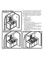
Preparing the cabinet
• Cut out the recess for one or several Vario
appliances in your worktop. Proceed as indicated
on the installation sketch. The installation sketch
contains the measurements of the space required
for the trim between the appliances. Several
appliances can also be installed in individual
recesses, as long as a minimum clearance of
50 mm (2 ´ ´ ) is kept to between the appliances.
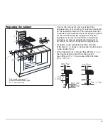
• As shown in the installation sketch, drill the
Ø 35 mm (1
3
/
8
´ ´ ) holes to secure the control knobs
in the cabinet front.
• If the cabinet front is thicker than 26 mm (1
1
/
32
´ ´ ),
the front must be routed from the back to
max. 26 mm (1
1
/
32
´ ´ ) on an area of 80 x 310 mm
(3
5
/
32
´ ´ -12
13
/
64
´ ´ ).
17
D > 1
1
/
32
''
D = 1
1
/
32
''
3
5
/
32
'' x
12
13
/
64
''
x
min.
13
/
64
''
min.
13
/
64
''
20
/
32
'' - 1
1
/
32
''
30
7
/
64
''
20
9
/
32
''
62
''
46
4
/
64
''
14
11
/
64
''
14
31
/
32
''
19
13
/
64
''
min.
1
31
/
32
''
min.
1
12
/
32
''
** 20
5
/
64
''
* 2
23
/
32
''
5
1
/
2
''
8
21
/
32
''
3
''
11
1
/
32
''
min.
4
9
/
64
''
max.
6
13
/
62
''
3
1
/
2
''
1
12
/
32
''
2
23
/
64
''
* Built-in depth of appliance 3
1
/
2
´´
at cable connection (middle, right)
** 20
7
/
8
´´ with cover hinge
Summary of Contents for VR 421-611
Page 1: ...Operating and Assembly Instructions VR 421 611 Electric Grill...
Page 2: ......
Page 23: ......

