


B
B
X
X
/
/
B
B
X
X
G
G
-
-
1
1
0
0
0
0
0
0
S
S
e
e
r
r
i
i
e
e
s
s
G
G
r
r
o
o
o
o
v
v
e
e
M
M
e
e
a
a
s
s
u
u
r
r
e
e
m
m
e
e
n
n
t
t
G
G
a
a
g
g
e
e
O
O
p
p
e
e
r
r
a
a
t
t
i
i
o
o
n
n
M
M
a
a
n
n
u
u
a
a
l
l
29
Operating Procedures
Inspecting Parts with the BXG-1000 Gage
Materials Needed:
•
BXG-1000 gage
•
Inspection report
•
Part
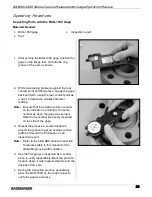
1. After zeroing the BXG-1000 gage, position the
gage on the flange face and into the ring
groove of the part, as shown.
2. While maintaining pressure against the rear
contact point and flange face, sweep the gage
back and forth, using the rear contact point as
a pivot, to locate the smallest indicator
reading.
Note:
Be sure that the small revolution counter
on the indicator is pointing to the same
number as when the gage was zeroed.
Refer to the number previously recorded
on the side of the gage.
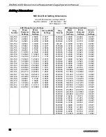
3. Repeat the process in several locations
around the groove to get an average groove
width and record the information on an
inspection report.
Note:
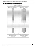
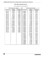
Refer to the 6B & 6BX Groove Inspection
Tolerances table in this manual for the
allowable groove width variation.
4. Use the first part you inspected as a control
piece to verify repeatability. Mark the part at a
location where it was inspected and record the
deviation from zero.
5.
During the inspection process, periodically
place the BXG-1000 on the control piece to
verify the gage’s accuracy.