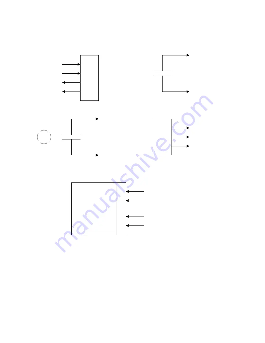
G-Scale Graphics APTC Operation And Installation Manual Download Page 6


Page 6 

Mag

net

IN+

Out

IN-

Motion Sensor

Track Reed Switch

Remote Start Switch

Start

Com

Start

SS 

(+5V from APTC)

Com

Com

Stop

+

-

T
T

Power Supply

7-25 VDC In

To Track

(10 Amps Max)

All Purpose Train Control

Wiring Diagram

Wireless     

Track    

Reed Switch    

APTC

Track Power In

Reed Switch

T
T

S
S

Summary of Contents for APTC

Page 1: ...ision C Updated 8 18 2021 Operation and Installation Manual G Scale Graphics 5860 Crooked Stick Dr Windsor CO 80550 970 581 3567 GScaleGraphics comcast net www GScaleGraphics net Revision A Updated 8...

Page 2: ...rolley line Use the Max Speed feature to limit speed when children are at the controls Manual speed control with user programmable momentum Automated Random Station Stops via track mounted reed switch...

Page 3: ...of the Speed Pot Emergency Stop Holding the Stop button or contact closure for more than 1 2 second at any time will initiate a quick stop Speed Pot Adjust the speed pot at any time to change the spe...

Page 4: ...each end of a track and Parameter 2 Option 6 it will run in back and forth trolley mode Stopping the train A running train can be stopped automatically after running for One Lap or after a Time Perio...

Page 5: ...when the track switch is activated by a magnet The green APTC LED will blink OFF whenever a start or stop command is received whether it is hardwired or wireless The red LED on the APTC wireless rece...

Page 6: ...rack Reed Switch Remote Start Switch Start Com Start SS 5V from APTC Com Com Stop T T Power Supply 7 25 VDC In To Track 10 Amps Max All Purpose Train Control Wiring Diagram Wireless Track Reed Switch...

Page 7: ...t train will leave the station make one lap returning to the station Option 5 can be used for Continuous Running no time out Parameter 4 Auto Start Interval Timer Sets the amount of time between autom...

Page 8: ...hing rapidly which indicates the save is complete Select the next Parameter Repeat the above as needed to view or make changes to other parameters using the DIP switch to select Exit Programming Mode...

Page 9: ...trical Power Input 7 25VDC reverse polarity protection prevents damage but will not operate Track Output Up to 10 amps Short circuit protection PWM Pulse Width Modulation 20 KHZ Control Inputs Normall...

Page 10: ...e of the power supply for 115 VAC U S Output voltage should be 24 VDC maximum for use with the G Scale Graphics Trackside R C or other Track Throttles But no adjustment should be necessary as received...

Reviews: