G-Lab GSC-4 User Manual Download Page 25

24  user manual GSC_4

Expression pedal 

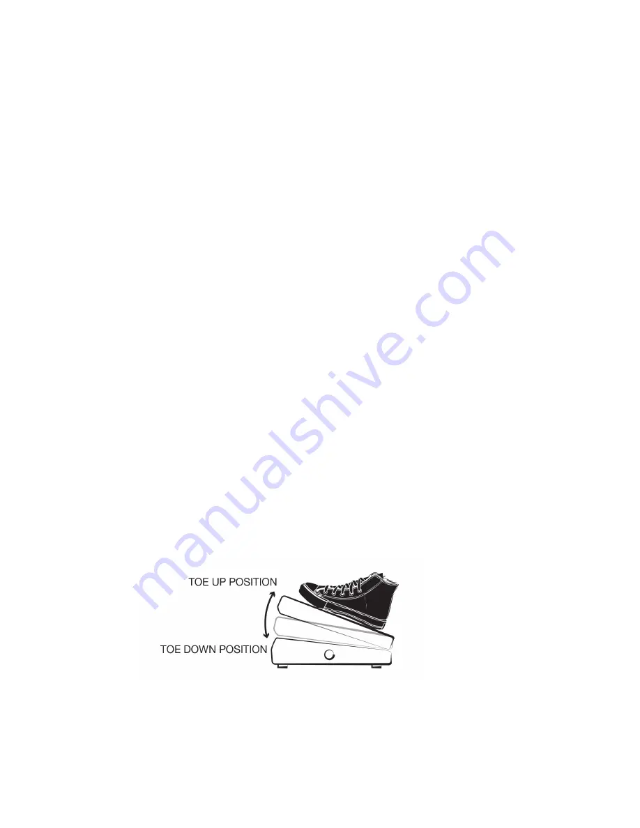
TOE- UP VALUE, TOE-DOWN VALUE

Connect the exp. pedal to the EXP PEDAL input.                     Pedal’s value is send by the GSC-4 using 
CTRL CHANGE number.

 Exp. pedal settings are placed in the Menu: MENU -> EXPRESSION PEDAL:

- NAME – Function’s name maximal 20 characters.

- STATE (ON/OFF) – Activate and deactivate exp pedal function.

- MIDI DEVICE – Define device that will be controlled with exp. Pedal.

- CTRL # - Control change number of controlled function (from 0 to 127).

- CHARACTERISTIC – Characteristic response of exp.pedal movement from upper   to lower pedal position:


• FAST/SLOW - Fast increase at the beginning, slow at the end.


• LINEAR - Proportionally within the entire range.


• SLOW/FAST - Slow increase at the beginning, fast at the end.

- TOE UP VALUE - Value for the up position (from 0 to 127).

- TOE DOWN VALUE - value for the low position (from 0 to 127).

- PERIOD - minimum interval between sending commands 4ms, 8ms,16ms, 32ms 64ms.

- CURRENT VALUE - currently sent value.

- CALIBRATION – pedal’s calibration.

CHARACTERISTIC of pedal’s response:

Typical expression pedals feature a linear characteristic (potentiometer taper response) and volume 

pedals feature a logarithmic characteristic. CURRENT VAL function enables to check characteristic of the 
pedal’s response. After pedal calibration set the CHARACTERISTIC as follows: LINEAR, TOE UP VAL: 0, TOE 
DOWN VAL: 127 and then set the pedal in its middle position. If the pedal features linear characteristics 
the CURRENT VAL will be about 63. If it is different it is possible to apply other characteristics from the 

CHARACTERISTIC function to correct the linearity of the pedal. It is also possible to use CHARACTERISTIC 
function to get the nonlinear characteristic of the pedal’s response.

Adjust the range of values which are send and change the direction of the given expression pedal function 

by the TOE UP VALUE and the TOE DOWN VALUE settings. To change the direction set the TOE UP VALUE 
bigger than the TOE DOWN VALUE. 

Summary of Contents for GSC-4

Page 1: ...instrukcja obs ugi bedienungsanleitung mode d emploi user manual GUITAR SYSTEM CONTROLLER...

Page 2: ...TCH outs 18 3 5 3 MIDI 18 4 PROGRAMMING MODE 19 4 1 Preset and MFS basic programming 20 4 1 2 Bank name 22 4 1 3 MFS name 22 4 1 4 LOOP section 22 4 1 5 SWITCH section 22 4 2 Settings programming 22 4...

Page 3: ...nce to radio communications However there is no guarantee that interference will not occur in a particular installation If this equipment does cause harmful interference to radio or television recepti...

Page 4: ...very high impedance circuit no tone coloration on guitar signal LOOP SPLIT mode that enables the connection of two stomp boxes at the amp s front input and three in the amp s FX loop without a ground...

Page 5: ......

Page 6: ...user manual GSC_4 5 1 OVERVIEW...

Page 7: ...t connect to effect input 6 EFFECT LOOP RETURN input connect from effect output 7 TFT Display 8 GSC 4 programming keyboard 9 MAIN OUT signal output 10 TUNER output 11 MAIN IN signal input 12 PRESET BA...

Page 8: ...user manual GSC_4 7 1 2 Keyboard description and layout 1_ ESC key 2_ ARROW UP key 3_ MENU key 4_ ARROW LEFT key 5_ OK key 6_ ARROW RIGHT key 7_ ARROW DOWN key...

Page 9: ......

Page 10: ...user manual GSC_4 9 2 BASIC OPERATION...

Page 11: ...ber 3 MFS type 4 Bank name 5 Selected MFS name 6 LOOP section with LOOPS and BUFFER indicators 7 SWITCH section with relays indicators 8 MIDI section with indicators for all 10 MIDI devices 9 LOOP SPL...

Page 12: ...user manual GSC_4 11 Figure 2 1 1 Preset MFS mode Figure 2 1 2 Loop Modifier MFS mode Figure 2 1 3 Switch Modifier MFS mode Figure 2 1 4 Midi Modifier MFS mode...

Page 13: ...w is displayed in the SETTINGS PROGRAMMING It is built almost always in the same way The only difference refers to the functions name and the field s quantity including their designations Use the keyb...

Page 14: ...cted text for editing At this instance there are few options Press OK to keep the text and move the cursor to the end of the text Press LEFT and RIGHT ARROWS to keep the text and move the cursor to th...

Page 15: ...ues is on the top left side No 1 in Figure 2 05 The INACTIVE field is the first active field after the screen is displayed At this instance there are few options Press OK to set the value to INACTIVE...

Page 16: ...user manual GSC_4 15 3 WORKING MODE...

Page 17: ...to the following mechanisms BANK color back round is always the same MFS number function and name are changing color back round depending on MFS function see figures 2 1 1 2 1 2 2 1 3 2 1 4 Fields an...

Page 18: ...y field with gray color 5 6 7 8 9 10 indicates that there is no defined MIDI device 3 3 Recalling the preset Press the MFS footswitch from 0 to 9 to recall the preset Controller will recall all preset...

Page 19: ...e the relays to switch Relays will not switch when a recalled preset or MFS doesn t change the LOOP S state In the first stage the signal is muted Then relays are switched and muting is off Recalling...

Page 20: ...user manual GSC_4 19 4 PROGRAMMING MODE...

Page 21: ...mode of the switch Fields 4 and 5 mean that switches are INACTIVE Select and recall the Bank and MFS footswitch to enter its programming For basic preset programming press OK Use the keyboard ARROWS...

Page 22: ...ctive for which MFS mode PRESET ON the section s field is set to on and causes the immediate reaction of hardware OFF the section s field is set to off and causes the immediate reaction of hardware PC...

Page 23: ...r 2 2 it is described how to move in the MENU setting Warning IF THE SETTINGS PROGRAMMING WAS ACTIVATED FROM THE MODIFIER THEN THE QUIT WILL RECALL THE NEAREST PRESET PRESET ON the section s field is...

Page 24: ...o assign up to a maximum of 20 such functions for each midi device To set the controller list proceed as follows MENU MIDI DEVICES MIDI DEVICE NAME CONTROLLER LIST Beside the controller s number it is...

Page 25: ...sending commands 4ms 8ms 16ms 32ms 64ms CURRENT VALUE currently sent value CALIBRATION pedal s calibration CHARACTERISTIC of pedal s response Typical expression pedals feature a linear characteristic...

Page 26: ...of signal in proportion to the full signal range Controller enables to receive PROG CHANGE and CONTROL CHANGE commands from an external MIDI device for remote control Commands enable to remotely recal...

Page 27: ...the loop 3 will permanently switch ON The information on the main display will turn to SPLIT WILL CHANGE Then switch off the controller After reconnecting the power of the controller loops will split...

Page 28: ...user manual GSC_4 27 5 CONNECTING GSC 4 ACCESSORY...

Page 29: ...adapter is required Many amps are equipped with a female Jack footswitch input If your amp is equipped with such type of connector please check on www glab com pl or ask your dealer and amp manufactur...

Page 30: ...AH PAD input The wah pad is a touch sensor enabling to switch automatically on off state of the wah wah or the WHAMMY effect without the effect switcher The WAH PAD can also be used for a typical anal...

Page 31: ...ectronic equipment Parties collecting such equipment organise a system including local collection points shops and other units allowing to return such equipment This Directive assures an user free of...

Page 32: ......

Page 33: ......

Page 34: ...Company address Elzab Soft sp z o o ul Kruczkowskiego 39 41 813 Zabrze Poland phone 48 32 370 63 08 Sales Export Department e mail glab glab com pl phone 48 32 370 63 08 Technical Support e mail help...

Reviews: