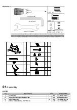
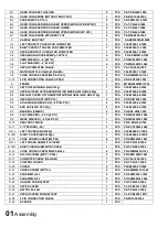
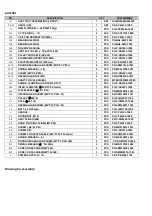
background image

part list 


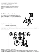
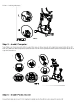
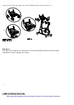
Drawing for assembly

’ 


NO. 

DESCRIPTION 

QTY 

BOM NUMBRE 

SEAT POST ASSEMBLING (40*80*2T) 

SET 

AAEB1000FA049000 

F-LR 

PEDAL(L/R) 

SET 

PS-T-PB-433-1080 

GEM FLYWHEEL (

φ

240*45W(11kg)) 

PCS 

PH-FDX24045-1002 

G-1 

C TYPE RIGN (

φ

17) 

PCS 

PD-KCO11700-1002 

G-2 

COIL FOR GENERATOR (900L) 

PCS 

PH-T-PB-417-1000 

G-3 

BEARING (6203RS) 

PCS 

PH-BA2-6203-1005 

G-4 

BEARING (6203RS) 

PCS 

PH-BA2-6203-1005 

G-5 

ONE WAY BEARING 

PCS 

PH-P-PB3485-1000 

G-6 

PROTECT COVER (

φ

78*

φ35*12.5W) 

PCS 

PH-P-PB2943-1100 

G-7 

PULLEY WITH AXLE (J8*

φ30) 

PCS 

PH-P-PB3254-1000 

G-8 

ALUMINUM SUPPORT FOR EMS 

PCS 

PH-P-PB3397-1000 

G-9 

ELECTRIC MAGNETIC (600mm) 

PCS 

PE-P-PB3549-1000 

G-10 

ROUND HEXANGULAR SCREW (M10*P1.5*20L) 

PCS 

PD-SOM21020-1041 

G-11 

SPRING WASHER (

φ

10) 

PCS 

PD-WS221000-1041   

G-12 

SCREW (M5*P0.8*80L) 

PCS 

PD-P-PB3257-1041 

G-13 

HEXANGULAR NUT (M5) 

PCS 

PD-NHM20500-1041 

SHAFT FOR IDLE WHEEL   

PCS 

MTEB1000FW047005 

H-1 

SPRING CLAMPING (

ODΦ16*Φ2.0*35T) 

PCS 

PH-P-PB1226-1000   

H-2 

IDLER CLAMPING (

Φ

24*

Φ37*20.5mmL) 

PCS 

PH-P-PB3851-1000 

H-3 

FLAT WASHER (

Φ

8*

Φ19*2t) 

PCS 

PD-WN220819-1041 

H-4 

HEXANGULAR SCREW (M8*P1.25*25L*3t) 

PCS 

PD-SHM10825-1141 

PULLEY (

Φ

260*6) 

PCS 

PH-PJ6A2601-1100 

I-1 

AXLE (

Φ

20*153) 

PCS 

PR-P-PW5427-1000 

I-2 

HEXANGULAR SCREW (M8*P1.25*12L*5t) 

PCS 

PD-SHM20812-1102 

I-3 

BELT (J6 1126m/m) 

PCS 

PH-LJ6M1126-1000 

SADDLE 

PCS 

PS-T-PB-325-1080 

J-1 

ROUND NUT (M10) 

PCS 

PH-T-PB-269-1000 

J-2 

SEAT SLIDER (45#) 

PCS 

PR-P-PW5429-1000 

J-3 

KNOB FOR SEAT SLIDER (M10*30) 

PCS 

PH-T-PB-286-1000 

J-4 

SCREW ( 

φ8*φ16*2t) 

PCS 

PD-WN210816-1041                                             

J-5 

SCREW SET 

PCS 

PH-P-PB3418-1000 

J-6 

SCREW FOR SEAT STABLE ( M8*P1.25*35L 6m/m) 

PCS 

PD-SOM20835-1041   

J-7 

SPRING WASHER (

φ

8) 

PCS 

PD-WS220800-1041                                             

ROUND HEXANGULAR SCREW (M7*P1.0*30l 30#) 

PCS 

  PD-SOM30730-1082 

K-1 

SPRING WASHER (

Φ

7*2t 65Mn) 

PCS 

PD-WS310700-1082 

K-2 

CONE CROSS SCREW (M3*30L) 

PCS 

PD-SBM30330-1082 

K-3 

CONE CROSS SCREW (M5*10L 30#) 

PCS 

PD-SWM20514-1082 

POWER SUPPLY 6V 1A 

PCS 

PE-P-PB4386-1100 

Summary of Contents for TZ-7016

Page 1: ...TZ 7016...

Page 2: ...s Manual 01 Assembly Your bike will require a small amount of assembly You will find everything you need included in the box 02 Get to know your bike Take time to get to know your new bike it will hel...

Page 3: ...ate exercise clothing when using the bike Do not wear loose clothing that could become caught in the bike 7 If you feel pain or dizziness while exercising stop immediately and cool down 8 The pulse se...

Page 4: ...1 Screw M3 30L 3 SCREWS M5 P0 8 10L 3 Spring Washer 2T 2 STEP 6 STEP 4 STEP 4 STEP 6 01 Assembly part list NO DESCRIPTION QTY BOM NUMBRE A COMPUTER 1 PCS PE SR66000010706 A 1 ADJUSTABLE COMPUTER BRACK...

Page 5: ...1080 D 3 BELLOW COVER OF TRANSPORTAITON WHEEL 432U ABS 210g 1 PCS PLEB1000 06 1080 D 4 HEXANGULAR NUT M16 P1 5 2 PCS PD NHI21600 1082 D 5 ADJUSTABLE REAR CAP 80 30L PVC 4 PCS PLEB1000 08 1002 D 6 END...

Page 6: ...WHEEL 1 PCS MTEB1000FW047005 H 1 SPRING CLAMPING OD 16 2 0 35T 1 PCS PH P PB1226 1000 H 2 IDLER CLAMPING 24 37 20 5mmL 1 PCS PH P PB3851 1000 H 3 FLAT WASHER 8 19 2t 1 PCS PD WN220819 1041 H 4 HEXANGU...

Page 7: ...exploration drawing STEP 1 Install Pedals...

Page 8: ...Bottle Cage Install the Handlebar Post First screw one M5 screw upper out of the handlebar post C with screwdriver and insert bottle cage on it Then screw it back upper screw and screw another one ti...

Page 9: ...justable computer bracket with four M5 screw A 2 Make four cables through the computer back cover Connect four computer cables with computer Screw computer back cover to computer with two screws 2 3 5...

Page 10: ...ss screw C 3 1 2 3 Well done Your bike is now ready for use Please go to the computer operation section in this manual for instructions on how to operate your console COMPUTER INSTRUCTION Before opera...

Page 11: ...is glittering user may press UP and DOWN button to select user 1 user 2 to user 9 3 2 Preset personal data incl AGE WEIGHT HEIGHT SEX And press MODE button for confirmation drawing 3 drawing 4 4 Manua...

Page 12: ...set level is 1 drawing 11 10 11 5 2 After load level selected you may preset function values for TIME DISTANCE CALORIES and PULSE by turning UP DOWN button and press MODE confirmation drawing 12 15 5...

Page 13: ...on the handgrip And the LCD will display for 8 seconds until computer finish measuring 10 3 LCD will display BODY FAT advice symbol BODY FAT percentage and BMI for 30 seconds REFERENCE B M I Body mas...

Page 14: ...t target Calories will count down from preset time to 0 Each preset increment or decrement is 10 cal from 0 to 990 cal PULSE The user may have heart rate figures display after holding both hands on ha...

Reviews: