


Section 40
00-02-0893
2014-07-18
-
7 -
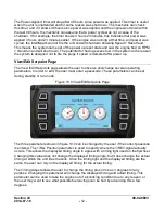
Spark kV Page
Once the system has entered the normal running mode, the display offers some unique insight
into the operation of an ignition system. As mentioned in the overview, one of the key features
is the ability to display actual spark gap breakdown voltage. Since the voltages required to
breakdown the gap are in the order of kilovolts, we refer to these parameters as kV values.
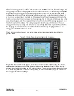
Pressing the Spark Page button will take the user to the page that shows all of the plug
’s kV
values. Figure 5.0 shows the spark page screen.
Figure 5.0 Spark Page
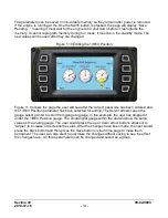
Figure 5.0 shows what a 16 cylinder engine spark kV page would look like. The leftmost
vertical bar graph shows how much kV the coil is supplying. The individual cylinder graphs
show what each plug requires for breakdown. Underneath each bar is the value in numeric
form. At a glance, this page tells the user that all plugs are firing and that they are all firing with
similar values. Plugs that are not firing near the average may need to be inspected. It may only
be that the plug gap is different, but it may indicate something more serious.
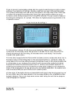
There are diagnostics for each cylinder that tell the user if he has any one of the following
conditions:
1. Open primary wire
2. Shorted primary wire
3. Open or disconnected plug wire
There is a button for displaying the average kV for each cylinder. The average is based on
samples taken over a period of 10 seconds.


