FW Murphy IntelliSpark Operation Manual Download Page 19


Section 40 


00-02-0893 

2014-07-18 

17 -


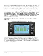
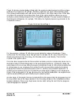
Figure 16 shows a typical display of data after the engine is started using one of the camless 
methods. The engine is a 16 cylinder; therefore, eight coils are used in the test firing phase. 
The cylinders used always start with the second cylinder in the firing order, which in this case 
is cylinder 1R according to the firing order. Each of the eight cylinders is fired once every 
revolution, and its timing is based on the Timing RPM schedule. The user would normally set 
the timing to 0.00 degrees, for example, TDC where the highest pressure is generated on the 
compression stroke.  

Figure 16.0 Cam Score Page 3 


For this example, cylinders 1R-4R show a good distinction between the strokes. These 
numbers are the time delay values that get used to calculate the kV value. Since the kV is 
directly proportional to the time delay, the time data can be used directly. This is further 
covered in the ignition class.  

From this data, it appears that the first and third revolutions are the compression stroke due to 
the higher values on these firings than on the second and fourth revs. Cylinder 5L shows the 
same value so this is a case where there was no distinction made on this cylinder possibly due 
to a fouled plug or very small gap. But cylinder 5L will not prevent this engine from starting 
because the minimum required score was set to 12, and the score obtained reached 21. A 
perfect score would have been 24 if cylinder 5L provided higher readings on its compression 
stroke. If the compression in 5L was gone due to a mechanical malfunction, the engine would 
start but would exhibit poor performance due to a dead cylinder.  

Another piece of information that can be deduced from this page is that the plug gaps may not 
be very uniform due to the large variation in the time delay values on the compression stroke 
between cylinders. This is not a major issue but one worth noting the next time the plugs are 
cleaned/regapped or replaced.  


Summary of Contents for IntelliSpark

Page 1: ...00 02 0893 2014 07 18 Section 40 IgnitionSystems Operation Manual...

Page 2: ...BEFORE BEGINNING INSTALLATION OF THIS FW MURPHY PRODUCT Read and follow all installation instructions Please contact FW Murphy immediately if you have any questions...

Page 3: ...equirements 3 Power Supply 3 Ignition Enable 3 Crank and Cam Signals 3 Operating 4 Display Functions Main Menu 4 Engine Start Up 5 Engine Run Mode 6 Spark kV Page 7 Engine View Page 9 Diagnostic Log P...

Page 4: ...THIS PAGE INTENTIONALLY LEFT BLANK...

Page 5: ...efer to the Specifications section in the Installation Booklet for details Note that the system also requires a few seconds after power is applied before it is able to start firing If the system is be...

Page 6: ...his button to be active For example if the engine is running this button will not be active System Setup This button takes the user to the passcode screen and then to the setup menu For details on wha...

Page 7: ...s the page contents when the system is in the standby mode and is ready to start the engine In this example the timing schedule A is active and the timing is set for 10 0 degrees BTDC The Tank voltage...

Page 8: ...s relay turns on the fuel valve the engine should start to pick up speed Figure 3 0 Cranking Engine Run Mode Once the engine RPM exceeds the Crank Run RPM the system will go into the normal run mode O...

Page 9: ...engine spark kV page would look like The leftmost vertical bar graph shows how much kV the coil is supplying The individual cylinder graphs show what each plug requires for breakdown Underneath each b...

Page 10: ...gy gauge will also rise tracking the tank voltage The energy gauge can provide a good indication of the auto energy control loop operating and can also be used to help determine or predict the end of...

Page 11: ...alue Figure 7 0 Engine Block View Another feature of the engine block page is the indication of the wire color of the primary lead that should be wired to the indicated cylinder The primary harness co...

Page 12: ...possible diagnostic conditions for each cylinder are displayed in a table format Any occurrence of one of the three fault conditions will cause the appropriate box to be filled in red and this box wi...

Page 13: ...ce of the 1 REV pulse and the trailing edge is negative indicating the trailing edge happened after the 1 REV pulse These are normal values The CAM parameters are grayed out if the unit is programmed...

Page 14: ...int Page The View Edit Setpoints page allows the user to observe and change several operating parameters In order to edit the user must enter a passcode These parameters can be set during standby or r...

Page 15: ...rrect passcode has been entered and the 1 REV Position parameter has been selected for editing The Select arrows cause the gauge select pointer to scroll from gauge to gauge In the example the user ha...

Page 16: ...eled More which will bring him to another page that gives him access to two factory set parameters Figure 12 0 Factory Setpoints These parameters are set during a final factory test They affect the kV...

Page 17: ...the Active Shutdown would show normal shutdown and it would be saved and time stamped below the Active Shutdown line The Alarms include some shutdowns as well as detected fault conditions that are not...

Page 18: ...screen after the user pressed the Alarm Ack Button Figure 14 0 Ignition Fault screen view In the above example the user is asked to view the Diagnostic Log Page Figure 15 0 shows the Diagnostic Log p...

Page 19: ...ed directly This is further covered in the ignition class From this data it appears that the first and third revolutions are the compression stroke due to the higher values on these firings than on th...

Page 20: ......

Reviews: