background image


www.futurelight.com


24


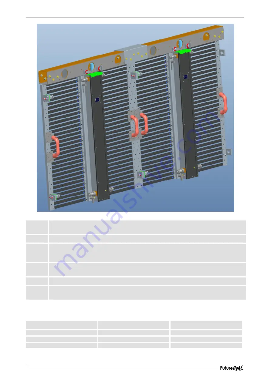
Mount the truss bars to the truss via suitable steel ropes. Use one steel rope and one secondary 
safety element per truss bar.


Interconnect the truss bars with their U profiles.  

Mount the first display to each truss bar. For this, push the display’s bolts from below through 
the truss bar and lock them with the lock pins. Further secure the displays by turning the 
horizontal bolts by 90°. 

Mount all other displays from top to bottom by fastening the vertical bolts and locking pins and 
the horizontal rotating bolts. 

Make the power and data cabling (

 chapter 8). 

Install the sending card and start the configuration with the PC program [LED Manager] (


chapter 8). 

 
The following table shows the maximum number of displays that can be suspended with a single truss bar— 
indoor and outdoor. 


Model 

Indoor   

Outdoor   

SVS 18.75 

max. 12 

max. 7 

SVS 25 

max. 10 

max. 5 

SVS 37.5 

max. 10 

max. 5 

Summary of Contents for SVS-18.75

Page 1: ......

Page 2: ... PC Software Signalverteilung per UTP Kabel PowerCon Ein und Ausgänge Traversenhalter und Kabel für Signal und Strom versorgungsverteilung als Zubehör erhältlich TRUSS BAR No 51843211 SVS 37 5 No 51843221 SVS 25 No 51843231 SVS 18 75 Modular LED video display for outdoor use IP63 Extra bright and colorful projection of videos animations and graphics Ideal for rental companies stage fair constructi...

Page 3: ...CHLÜSSE HERSTELLEN 12 9 REINIGUNG UND WARTUNG 14 10 TECHNISCHE DATEN 15 Mindestsystemanforderungen 16 Zubehör 16 Table of Contents 1 INTRODUCTION 17 2 SAFETY INSTRUCTIONS 18 3 OPERATING DETERMINATIONS 19 4 COMPONENTS 20 5 MOUNTING ELEMENTS AND CONNECTIONS OF A DISPLAY 21 6 CONTROL COMPONENTS 22 7 INSTALLATION 23 9 MAKING THE CONNECTIONS 25 10 CLEANING AND MAINTENANCE 27 Minimum System Requirements...

Page 4: ...aben müssen entsprechend qualifiziert sein diese Bedienungsanleitung genau beachten die Bedienungsanleitung als Teil des Produkts betrachten die Bedienungsanleitung während der Lebensdauer des Produkts behalten die Bedienungsanleitung an jeden nachfolgenden Besitzer oder Benutzer des Produkts weitergeben sich die letzte Version der Anleitung im Internet herunter laden Diese Bedienungsanleitung gil...

Page 5: ... es zu Beschädigungen der Netzleitung zu Brand oder zu tödlichen Stromschlägen kommen Die Kabeleinführung oder die Kupplung am Gerät dürfen nicht durch Zug belastet werden Es muss stets eine ausreichende Kabellänge zum Gerät hin vorhanden sein Andernfalls kann das Kabel beschädigt werden was zu tödlichen Stromschlägen führen kann Achten Sie darauf dass die Netzleitung nicht gequetscht oder durch s...

Page 6: ... Anlage den grundlegenden Anforderungen entspricht und nach anerkannten Regeln der Technik errichtet wurde Der Betreiber hat die elektromagnetische Verträglich keit seiner Anlage sicherzustellen Umgebungsbedingungen Das F Zeichen bedeutet Diese Leuchte darf auf normal entflammbaren Oberflächen installiert werden Das Bildzeichen bezeichnet den Mindestabstand zu beleuchteten Gegenständen Der Abstand...

Page 7: ...turelight com 7 4 KOMPONENTEN Nachfolgend finden Sie alle Komponenten die zum Betreiben eines Displays benötigt werden Einige der Komponenten können auch für andere Produkte von FUTURELIGHT eingesetzt werden ...

Page 8: ...s 4 6 Griff 7 Stromeingang zum Anschluss an eine Steckdose oder an den Stromausgang eines vorhergehenden Displays 8 Stromausgang zur Stromversorgung des nachfolgenden Displays 9 RJ45 Schnittstellen zum Anschluss an die Senderkarte oder an ein vorhergehendes bzw nachfolgendes Display beide Buchsen können beliebig als ein Ein und Ausgang verwendet werden 10 Statusanzeigen SIGNAL blinkt grün Signal w...

Page 9: ...ive Videosignalen sollte der Videoprozessor RGBlink VSP 516 verwendet werden PCI Senderkarte 1 Status LEDs Rot keine Spannungsversorgung Grün DVI Signal wird empfangen 2 RJ45 Schnittstellen zum Anschluss an das erste Display in der Kette linke Buchse U rechte Buchse D 3 USB Buchse zum Anschluss an die USB Schnittstelle des Computers über das mitgelieferte Verbindungskabel 4 DVI Schnittstelle zum A...

Page 10: ...des Gerätes Versuchen Sie niemals die Installation selbst vorzunehmen wenn Sie nicht über eine solche Qualifikation verfügen sondern beauftragen Sie einen professionellen Installateur Unsachgemäße Installationen können zu Verletzungen und oder zur Beschädigung von Eigentum führen Der Unternehmer hat dafür zu sorgen dass sicherheitstechnische und maschinentechnische Einrichtungen vor der ersten Inb...

Page 11: ...ie Displays über die beiden seitlichen Verriegelungsbolzen durch Drehen um 90 4 Verbinden Sie alle weiteren Displays miteinander von oben nach unten über die vertikalen Verriegelungsbolzen und die Spliten sowie seitlich mit den drehbaren Verriegelungsbolzen 5 Stellen Sie die Strom und Datenverkabelung her Kapitel 8 6 Installieren Sie die Senderkarte und starten Sie die Konfiguration mit dem Progra...

Page 12: ...eien PCI Steckplatz des Computers Schließen Sie die Senderkarte an die Spannungsversorgung des Computers an Bringen Sie die Abdeckung wieder an 3 Verbinden Sie den Computer wieder mit der Stromversorgung Starten Sie den Computer 4 Verbinden Sie die DVI und die USB Schnittstellen der Senderkarte mit denen des Computers über die mitgelieferten Kabel 5 Die Grafikkarte des Computers muss für den Betri...

Page 13: ... V Betrieb Verbinden Sie jeweils den Stromausgang POWER OUT eines Displays mit dem Stromeingang POWER IN des nachfolgenden Displays mit den als Zubehör erhältlichen Stromkabeln Artikel 51843212 51843222 51843232 Schließen Sie jeweils das erste Display in der Kette mit dem als Zubehör erhältlichen Netzkabel Artikel 51843272 ans Netz an Verbinden Sie dazu den Stromeingang POWER IN des Displays mit e...

Page 14: ...gungen und dürfen sich nicht unwuchtig drehen 4 Die elektrischen Anschlussleitungen dürfen keinerlei Beschädigungen Materialalterung z B poröse Leitungen oder Ablagerungen aufweisen Weitere auf den jeweiligen Einsatzort und die Nutzung abgestimmte Vorschriften werden vom sachkundigen Installateur beachtet und Sicherheitsmängel behoben Das Gerät sollte regelmäßig von Verunreinigungen wie Staub usw ...

Page 15: ...zahl Displays max 1280 pro Senderkarte Betriebstemperatur 10 bis 45 C Luftfeuchte 10 bis 95 Maße 900 x 900 mm Gewicht 17 kg 51843220 FUTURELIGHT SVS 25 LED Display 80x80 Spannungsversorgung 100 240 V AC 50 60 Hz Gesamtanschlusswert 160 W Auflösung 32 x 32 Pixel Pixelabstand 25 mm Pixeldichte 1600 m LED Typ DIP 546 Signalanschluss 2 x RJ45 Neutrik Helligkeit 5500 cd m Nits Abtastung Progressive Sca...

Page 16: ...0 mm Gewicht 13 kg 51843271 PCI Senderkarte und Software Signaleingang DVI Steuersignal USB Signalausgang 2 x RJ45 Maße LxBxH 160 x 130 x 48 mm Gewicht 1 3 kg Mindestsystemanforderungen Windows 7 Celeron 2 4 GHz 1 GB RAM Grafikkarte mit freiem DVI oder HDMI Ausgang 32 MB Freier USB Anschluss Zubehör 51843273 PVS SVS Videoprozessor 51843272 SVS Netzzuleitung 5m 51843270 SVS Signalkabel 20m 51843212...

Page 17: ... this device has to be qualified follow the instructions of this manual consider this manual to be part of the total product keep this manual for the entire service life of the product pass this manual on to every further owner or user of the product download the latest version of the user manual from the Internet For your own safety please read this user manual carefully before you initially star...

Page 18: ...he power cord Never operate next to sources of heat or cold Disregard can lead to power cord damages fire or mortal electrical shock The cable insert or the female part in the device must never be strained There must always be sufficient cable to the device Otherwise the cable may be damaged which may lead to mortal damage Make sure that the power cord is never crimped or damaged by sharp edges Ch...

Page 19: ...allation The operator must make sure that his installation complies with the basic requirements and follows the general rules of technology The operator must make sure that his installation complies with the electro magnetic compatibility Installation Do not shake the device Avoid brute force when installing or operating the device When choosing the installation spot please make sure that the devi...

Page 20: ...www futurelight com 20 4 COMPONENTS The following describes all the components needed to operate an LED display Some of the components are used for other FUTURELIGHT products as well ...

Page 21: ...olt for locking the connection bolt 4 6 Handle 7 Power input for conection to a power outlet or the power output of a previous display 8 Power output for power supply of a subsequent display 9 RJ45 ports for connection to the sending card or a previous or subsequent display both jacks can be used as input or output 10 Status indicators SIGNAL flashes green signal is received lights green no signal...

Page 22: ... for pre recorded video content For live show playback the RGBlink VSP 516 video processor should be used PCI Sending Card 1 Status LEDs red power supply failure green DVI signal is detected 2 RJ45 ports for connecting the first display in the chain left jack U right jack D 3 USB port for connection to the USB port on the computer via the included adapter cable 4 DVI input for connection to the DV...

Page 23: ...red with appropriate secondary safety elements e g steel rope so that no part of the installation can fall down if the main attachment fails You must only use safety bonds complying with DIN 56927 quick links complying with DIN 56927 shackles complying with DIN EN 1677 1 and BGV C1 carbines The safety bonds quick links shackles and the carbines must be sufficiently dimensioned and used correctly i...

Page 24: ...s Further secure the displays by turning the horizontal bolts by 90 4 Mount all other displays from top to bottom by fastening the vertical bolts and locking pins and the horizontal rotating bolts 5 Make the power and data cabling chapter 8 6 Install the sending card and start the configuration with the PC program LED Manager chapter 8 The following table shows the maximum number of displays that ...

Page 25: ... card into a free PCI slot of the computer Connect the sending card to the computer s power output Replace the case 3 Apply power to the computer and start it 4 Connect the DVI and USB ports of the sending card to the computer s ports via the supplied cables 5 The computer s graphics card must be configured for use with the sending card documen tation LED Manager 6 If the green status LED of the s...

Page 26: ...es when operated with 230 V and 6 when operated with 115 V In each case connect the power output POWER OUT of a display to the power input POWER IN of the subsequent display using the optional power cables items 51843212 51843222 51843232 Connect each first display in the chain to the mains by connecting the optional power cable item 51843270 to the display s power input POWER IN and then to a mai...

Page 27: ...ring e g material abrading or damages and must not rotate with unbalances 4 The electric power supply cables must not show any damages material fatigue e g porous cables or sediments Further instructions depending on the installation spot and usage have to be adhered by a skilled installer and any safety problems have to be removed We recommend a frequent cleaning of the device Please use a soft l...

Page 28: ...mber of displays 1280 per sending card Operating temperature 10 to 45 C Humidity 10 to 95 Dimensions 900 x 900 mm Weight 17 kg 51843220 FUTURELIGHT SVS 25 LED Display 80x80 Power supply 100 240 V AC 50 60 Hz Power consumption 160 W Resolution WxH 32 x 32 pixels Pixel pitch 25 mm Pixel density 1600 m Pixel configuration DIP 546 Signal connection 2 x RJ45 Neutrik Display mode 5500 cd m Nits Brightne...

Page 29: ... Weight 13 kg 51843271 PCI Sending Card and Software Signal input DVI Command communication USB Signal output 2 x RJ45 Dimensions LxWxH Weight 160 x 130 x 48 mm 1 3 kg Minimum System Requirements Windows 7 Celeron 2 4 GHz 1 GB RAM Graphics card with free DVI or HDMI output 32 MB Free USB port Accesories 51843273 PVS SVS Video processor 51843272 SVS Power feed cable 5m 51843270 SVS Signal cable 20m...

Page 30: ...www futurelight com 30 NOTES ...

Page 31: ...www futurelight com 31 ...

Page 32: ...01 FUTURELIGHT 201 FUTURELIGHT 201 FUTURELIGHT 2014 4 4 4 Technische Änderungen ohne vorherige Ankündigung und Irrtum vorbehalten Every information is subject to change without prior notice 00077648 DOCX Version 1 0 ...

Reviews: