background image

106

GO to TABLE OF CONTENTS

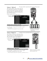
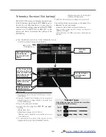
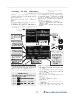
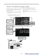
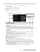
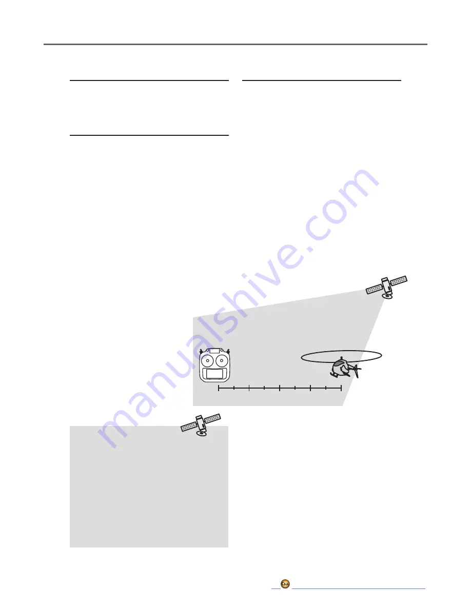
*Positioning time of GPS

When powered up, the SBS-01/02G begins to 

acquire GPS satellite data.  This process can 

take several minutes.  Please do not move the 

model during this process.  During acquisition, 

the LED on the SBS-01/02G will blink green; 

after the satellite's signals have been acquired, 

the LED will become solid green, and the GPS 

signal strength display on the transmitter will 

show three bars.

Moving the model before the satellites are fully 

acquired will cause a delay in acquiring the 

satellite signal.

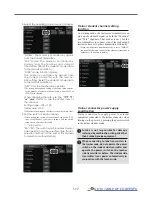
First, the set of a reference is required.

1. The model and transmitter to which the GPS 

sensor was connected are turned on. 

2. Tap to the [Preset] of "Reference" item.  

*Now, the position of the present model was set to 0 m.

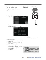
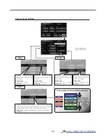
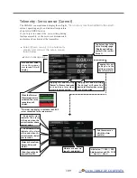
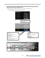
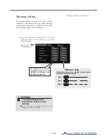
Setting a "too far" alarm distance 

1. Tap Alarm and choose from Buzzer, Voice, 

and Inhibit. 

2. Choose "Inhibit" for Vibrator if not using the 

vibrator alarm. If using vibrator, choose one 

of the three types. 

3. Tap Limit [m].

4. Adjust the rate using the "▼▼" "▼" "▲" "▲▲" 

buttons.

  Initial value: 1,000 m
  Adjustment range 0 m~3,000 m

(↑Limit 

 ↓Limit)

*When the screen is tapped for one second, the rate is reset to 

the initial value.

5. To terminate the input and return to the 

original state, push the HOME/EXIT button.

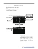
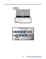
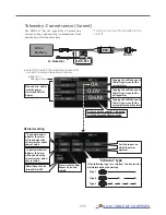
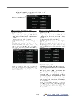
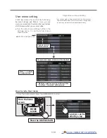
Setting a "too close" alarm distance

1. Tap Alarm and choose from Buzzer, Voice, 

and Inhibit. 

2. Choose "Inhibit" for Vibrator if not using the 

vibrator alarm. If using vibrator, choose one 

of the three types. 

3. Tap Limit [m].

4. Adjust the rate using the "▼▼" "▼" "▲" "▲▲" 

buttons.

  Initial value: 0 m
  Adjustment range 0 m~3,000 m

(↑Limit 

 ↓Limit)

*When the screen is tapped for one second, the rate is reset to 

the initial value.

5. To terminate the input and return to the 

original state, push the HOME/EXIT button.

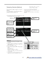
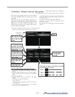
Distance

Telemetry 

Data

Summary of Contents for T16IZ

Page 1: ...1M23Z07702 WEB FULL MANUAL ...

Page 2: ... Lock Display 20 RF off mode 20 Switch SA SH 21 Volume 22 Slider 22 Digital Trims T1 T4 23 TABLE OF CONTENTS Monitor LED display 24 Stick Control 24 Stick Control Airplane Example 25 Stick Control Helicopter Example 26 Stick Control Multicopter Example 27 Stick Adjustment 28 Stick Mode 29 microSD card 30 Connector Plug 31 Receiver Nomenclature 32 Receiver s Antenna Installation 35 Safety precautio...

Page 3: ...rim 73 Function 74 Fail safe 76 System type 77 Trim setting 79 Throttle cut 80 Idle down 81 Swash ring Heli only 82 Swash Heli only except H 1 83 Stick alarm 85 Timer 86 Function name 88 Telemetry system 89 Sensor 91 Telemetry 94 Telemetry Receiver Battery 95 Telemetry Receiver Ext batt 96 Telemetry Temperature 97 Telemetry RPM sensor 98 Telemetry Altitude 99 Telemetry Altitude Variometer 100 Tele...

Page 4: ...125 Prog mixes Program mixing 126 Aileron differential 128 Flap setting 129 AIL Camber flap 130 AIL Brake flap 131 Aileron Rudder 132 Elevator Camber 133 Camber mixing 134 Airbrake ELE 136 Camber flap ELE 137 Rudder Aileron 138 Rudder Elevator 139 Butterfly 140 Trim mix 1 2 143 Snap roll Airplane only 144 Air brake Airplane only 145 Gyro 146 Ailevator 148 Acceleration 149 Motor 150 V tail 151 Wing...

Page 5: ...Basic 190 Expert Menu 193 Rudder Expert 194 Flight Tune Expert Aileron Elevator Expert settings 197 Swash Detail 198 Govenor Expert 201 MODEL MENU Multicopter 203 Condition select 204 AFR 206 Dual rate 207 Prog mixes Program mixing 208 Gyro 209 Common Operations used in function setup screen 211 Operations value setting 211 Operations related to flight conditions 211 Operations related to fine tun...

Page 6: ...riday 8 5 Central time to assist you For Service FUTABA Corporation of America 2681 Wall Triana Hwy Huntsville AL 35824 U S A Phone 1 256 461 9399 FAX 1 256 461 1059 https www futabausa com E mail service futabaUSA com Outside North America Please contact your Futaba importer in your region of the world to assist you with any questions problems or service needs Please recognize that all informatio...

Page 7: ...e the equipment Compliance Information Statement for Canada This device complies with Industry Canada license exempt RSS standard s Operation is subject to the following two conditions 1 this device may not cause interference and 2 this device must accept any interference including interference that may cause undesired operation of the device This equipment complies with IC radiation exposure limi...

Page 8: ...ry b Use of this product with other than models may be restricted by Export and Trade Control Regulations 3 Modification adjustment and parts replacement Futaba is not responsible for unauthorized modification adjustment or replacement of parts on this product No part of this manual may be reproduced in any form without prior permission The contents of this manual are subject to change without pri...

Page 9: ...icks may move and the propeller or rotor may rotate unexpectedly and cause injury Do not touch the engine motor or ESC during and immediately after use These items may become hot during use For safety fly so that the aircraft is visible at all times Flying behind buildings or other large structures will not only cause you to lose sight of the aircraft but also degrade the RF link performance and c...

Page 10: ...rger in a se cure location away from children Not doing so may cause electric shock or injury WARNING If the battery leaks liquid or generates an abnormal odor immediately move it to a safe place for disposal Not doing so may cause combustion If the battery liquid gets on your skin or clothing im mediately flush the area with tap water or other clean water Consult a doctor The liquid can cause ski...

Page 11: ...se erroneous operation Do not expose the card to shock and vibration and do not remove the card from the card slot while data is be ing written or read The data may be damaged or lost Keep wireless equipment batteries aircraft etc away from children Do not directly expose plastic parts to fuel oil ex haust gas etc If left in such an environment the plastic may be damaged Since the metal parts of t...

Page 12: ...tion function Selects a function that alerts the operator to various alarms by vibrating the transmitter in addition to sounding a buzzer Speech function A function is equipped which allows the system to provide telemetry data audibly This function can also be utilized with commercially available earphones Contents and Technical Specifications Specifications and ratings are subject to change witho...

Page 13: ... EXIT Button Color LCD Touch Display Digital trim T1 T4 Antenna SD card Slot PC Port Monitor LED Left Dial LD Right Dial RD Switch SC SD SG SH Switch SA SB SE SF J2 J3 J1 J4 Top Front T h e t r a n s m i t t e r c a n b e u s e d a s a game controller by connecting it to a computer with a USB cable Some games cannot be used ...

Page 14: ...ing LED Earpone Jack Stick tension adjustment port Back Bottom The LCD displays shown in this manual may vary from your own depending upon your model type LCD displays may also vary as a result of version upgrades or other changes The angle when the transmitter is placed can be changed by rotating the swing handle and tightening the screw ...

Page 15: ...n this can damage it The antenna is not removable CAUTION Do not grasp the transmitter antenna during flight Doing so may degrade the quality of the RF transmission to the model Do not carry the transmitter by the antenna The antenna wire may break making operation impossible Do not pull the antenna forcefully The antenna wire may break making operation impossible 1 2 3 4 5 Low power High power Hi...

Page 16: ...inch the wiring Connect the battery connector Press the tab to open the battery cover First insert two tabs Remove the battery cover Tab Battery cover This connector connects to the transmitter LT2F2000B LiPo Battery Press the tab to close the battery cover Click Click CAUTION Be sure to lock the battery cover If the battery cover comes off during flight the battery will fall off and crash ...

Page 17: ...en your hands are wet It may cause an electric shock Do not overcharge overdischarge the battery Overcharging Overdischarging a battery can result in burns fire injuries or loss of sight due to overheating breakage or electrolyte leakage CAUTION When the charger is not in use disconnect it from the AC outlet Do this to prevent accidents and to avoid overheating Charging a battery Charging LED Red ...

Page 18: ...nsmitter will begin emitting RF automatically after it confirms the surrounding RF conditions The status of the transmitter is displayed by LED at the upper part of the front of a T16IZ If THR stick is high a WARNING screen will appear Another warning will appear if a power supply is attached In Multicopter mode the THR position alarm will not appear If the Thr position alarm displays If the throt...

Page 19: ... Some pixels hold lighting Moreover some pixels go out And a screen may flicker Such condition is the characteristics of color LCD It is not failure Tapping the settings buttons for each value on the settings screen will cause value input buttons to appear at the top of the panel Value input buttons display at the top of the display Pressing and holding a value will return it to its default settin...

Page 20: ...eration is U MENU MON Press and Power ON Lock Display How to lock How to unlock 1 With the home screen displayed 2 Press the HOME EXIT button for about 1 second Key Icon is displayed and the keys will be disabled 1 Press the Home Exit button for about 1 second and the display will then become unlocked CAUTION The T16IZ s touch screen is very sensitive To avoid accidentally activating it during a f...

Page 21: ...rt lever SB 3 positions Alternate Long lever SC 3 positions Alternate Long lever SF 2 positions Alternate Long lever Alternate 2 positions Momentary 3 positions SH 2 positions Momentary Long lever SG 3 positions Alternate Short lever SE 3 positions Alternate Short lever Switch SA SH Self retum ...

Page 22: ...he center You can select a slide lever and set the movement direction on the setting screen of mixing functions The volume LD and RD knobs allow analog input The T16IZ transmitter beeps when the volume knob reaches the center position You can use each setting screen of the mixing functions to select volumes and define the direction of movement Volume LD RD ...

Page 23: ...tal trims Each time you press a trim button the trim position moves one step If you continue pressing it the trim position starts to move faster In addition when the trim position returns to the center the tone will change You can always monitor trim positions by referencing the LCD screen You can select the trim step amount and the display unit on the home screen on the T1 T4 setting screen withi...

Page 24: ...stick Throttle stick Engine motor Power Rudder stick Roll axis Example Stick Mode2 Red LED ON At startup Blinking Power switch is turned on with the throttle stick on the high side Power switch is turned on when any condition switch is activated in the ON state Blue LED ON Radio waves are being transmitted OFF Radio waves are in the OFF state Blinking 0 5 s Link mode Blinking 1 s Range check mode ...

Page 25: ...own Elevator is up Elevator is down Aileron stick To the right Neutral Neutral Nose Up Nose Down Middle High throttle Low throttle Roll Axis Control Yaw Axis Control Throttle Control Elevator stick UP moved to the bottom Elevator stick DOWN moved to the top Aileron stick To the left Pitch Axis Control Rudder stick To the right Neutral Rudder stick To the left Nose Right Nose Left Throttle stick MI...

Page 26: ...ral Nose Up Nose Down Middle High Pitch Up Pitch Down Slow Roll Axis Control Yaw Axis Control Throttle Pitch Control Elevator stick UP moved to the bottom Elevator stick DOWN moved to the top Aileron stick To the left Pitch Axis Control Rudder stick To the right Neutral Rudder stick To the left Nose Right Nose Left Throttle stick MIDDLE neutral Throttle stick HIGHT moved to the top Throttle stick ...

Page 27: ...ht Hovering Level flight Aileron stick To the right Neutral Neutral Nose Up Nose Down Roll Axis Control Yaw Axis Control Throttle Control Elevator stick UP moved to the bottom Elevator stick DOWN moved to the top Aileron stick To the left Pitch Axis Control Rudder stick To the right Neutral Rudder stick To the left Nose Right Nose Left Throttle stick MIDDLE neutral Throttle stick HIGH moved to the ...

Page 28: ...of stick lever tension The tension of the self return type stick lever can be adjusted Turn screw clockwise Stick tension maximum Stick tension minimum Turn screw counter clockwise 1 Use a screw driver to adjust the spring strength as you prefer by turning the adjusting screw of the stick you want to adjust Turning the screw clockwise increases the tension CAUTION Loosening the screw too much can ...

Page 29: ...ck matches the model operation System menu H W setting Select stick mode Calibrate after changing stick mode Back side Default AIL THR RUD ELE MODE1 AIL ELE RUD THR MODE2 AIL THR RUD ELE MODE3 AIL ELE RUD THR MODE4 J2 J3 Ratchet Spring Free Ratchet Free Spring ACT J2 stick J2 stick Spring Hard Spring Hard Spring Soft Spring Soft J2 stick J3 stick Spring Free Spring ACT J3 stick Ratchet Ratchet Fre...

Page 30: ...ed using a microSD card The T16IZ is capable of using SD and SDHC cards SD 32MB 2GB SDHC 4GB 32GB microSD card reader writer Saving model data and update files released from Futaba into the microSD card you can use those files on your T16IZ transmitter Equipment for reading and writing microSD cards is available at most electronics stores Stored data When you have a problem of saving or reading da...

Page 31: ... data recorded on the microSD card can be converted to CSV format by the telemeter log converter re leased on our home page When copying or moving a log file always select both FLI and FLD file Connector for trainer function When you use the trainer function connect the optional trainer cable between the transmitters for teacher and student You can set the trainer function on the Trainer Function ...

Page 32: ...king up your connectors If and of wiring are mistaken it will damage ignite and explode Don t connect to Extra Voltage before turning on a receiver power supply Before using the receiver be sure to read the precautions listed in the following pages Connector 1 through 6 outputs for the channels 1 through 6 7 B outputs of 7 channels and power 8 SB outputs of 8 channels or S BUS port S BUS Sevo S BU...

Page 33: ...HUB HUB S BUS servos Channel 1 18 Switch Switch to 8 SB port S BUS R7108SB CH Mode Mode A WARNING Please make sure that you use a battery that can deliver enough capacity for the number and kind of servos used Dry batteries cannot be used Power supply Please make sure that you use a battery that can deliver enough capacity for the number and kind of servos used Alkaline batteries cannot be used WA...

Page 34: ...ter changing the Channel mode LED Indication System Status LED FASSTest No signal reception Red Solid Receiving signals Green Solid Waiting for link Start 2second later Red Blink 1second FASST No signal reception Red Solid Receiving signals Green Solid Receiving signals but ID is unmatched Green Blink Waiting for link Red Blink FASSTest FASST Unrecoverable error EEPROM etc Alternate blink Green LE...

Page 35: ...e antennas away from each other as much as possible Larger models can have large metal objects that can attenuate the RF signal In this case the antennas should be placed at both sides of the model Then the best RF signal condition is obtained at any flying attitude 3 The antennas must be kept away from conductive materials such as metal carbon and fuel tank by at least a half inch The coaxial par...

Page 36: ...oint How to protect the receiver from vibration and water Wrap the receiver with something soft such as foam rubber to avoid vibration If there is a chance of getting wet put the receiver in a waterproof bag or balloon Receiver s antenna Never cut the receiver s antenna Do not bind the receiver s antenna with the cables for servos Locate the receiver s antenna as far as possible from metals or car...

Page 37: ...g S BUS S BUS2 special settings and mixes in your transmitter may be unnecessary The S BUS S BUS2 servos memorize the number of channels themselves settable with the T16IZ The S BUS S BUS2 system and conventional system receiver conventional CH used can be mixed Receiver R7108SB Battery FR2F1800 Optional Switch HSW L Throttle servo BLS173SV Optional Aileron servo BLS174SV 2 Optional Elevator servo...

Page 38: ...rt S BUS Port 8 SB Hub Hub Hub Hub Servo S BUS2 Servo S BUS Servo S BUS2 servo Connection is possible Mixed connection of S BUS and S BUS2 is possible S BUS2 gyro Connection is possible S BUS servo Connection is impossible Telemetry sensor Connection is impossible S BUS2 GYRO CH Mode is set to ModeB D Telemetry Sensors S BUS servos and gyros and S BUS2 servos and gyros must be used in the correct ...

Page 39: ...e S BUS device as shown in the figure 2 Turn on the transmitter power 3 Call the setup screen Servo System Menu S BUS servo Sensor Linkage Menu Sensor 4 Perform setting in accordance with each screen 5 This sets the channel and other data for each S BUS servo or telemetry device to be used with the S BUS device or receiver WARNING Do not disconnect or turn transmitter power OFF while S BUS servo a...

Page 40: ... User s name System timer This shows the accumulated time since the latest reset Each model Total Hour Minute Second This is the Home screen and descriptions of its menus Use your finger to operate the touch screen Menu Model menu Tap the Icon to call Model Menu screen Menu System Linkage Model select Tap the button to call each Menu screen Battery Indicator When battery is low the alarm will beep...

Page 41: ... Select System type at the Linkage menu and access the setup screen shown below by tapping the screen 4 When you use two receivers on one model you must change from Single to Dual Only two receivers can be used In Dual two setting items come out Input respectively 5 Battery fail safe voltage can be changed from the initial value of 3 8V here Only in FASSTest T FHSS Mode 6 Link is tapped The transm...

Page 42: ...response of the sensor data display becomes slower but stick response will improve Initial value 1 0s Adjustment range 0 1s 2 0s 9 ACT will be chosen if telemetry is used It is INH when not using it When you use two receivers please be sure to setup a Rx1 and Rx2 in the dual mode Telemetry function cannot be used for the 2nd receiver FASSTest18CH Telemetry function cannot be used for the dual rece...

Page 43: ...te that model ID function can not be used on other systems Link is required when a new model is made from a model selection Model 1 Receiver Add new model data Link Select a model in Model Select Link with a receiver that matches the model Link Link Model 2 Receiver Model 3 Receiver 1 3 Model 1 Model 2 Model 3 2 1 3 Model 1 Model 2 Model 3 2 1 3 Model 1 Model 2 Model 3 2 Rx 1 Rx 2 Rx 3 Select Mode...

Page 44: ...le simultaneously operating the controls Have an assistant stand by the model to confirm that all controls are completely and correctly operational You should be able to walk approximately 30 50 paces from the model without losing control 2 If everything operates correctly return to the model Set the transmitter in a safe yet accessible location so it will be within reach after starting the engine...

Page 45: ...The channel assignment of the T16IZ is different from that of our existing systems Note that even for the same airplane model when the wing type and tail type are different the channel assignment may be different The channel assigned to each function can be checked at the Function of the Linkage menu Airplane basic setting procedure If the direction of the servo is incorrect adjust the direction w...

Page 46: ...set for each condition and a cut switch which will turn OFF the delay can be chosen Trim amounts can be fine tuned by setting a VR You can also set the auto mode which will link Airbrake to a stick switch or dial A separate stick switch or dial can also be set as the ON OFF switch 8 Addition of flight conditions The Condition select function automatically allocates the Condition 1 for each model C...

Page 47: ...e helicopter functions of the T16IZ Adjust the actual values etc to match the fuselage used 3 Flight condition addition The transmitter can install up to eight flight conditions per model The Condition select function automatically allocates five conditions for helicopter General setting Normal Idle up1 Idle up2 Idle up3 Hold Note Delete conditions you have not set up and will not use Otherwise yo...

Page 48: ...ately 5º 6º Set the pitch at hovering with the stick position at the 50 point as the standard Stability at hovering may be connected to the throttle curve Adjustment is easy by using the hovering throttle function and hovering pitch function together Pitch curve Idle up 1 The idle up 1 pitch curve function creates a curve matched to airborne flight Set to 7º 12º as standard 4 Fuselage linkage Conn...

Page 49: ...hat allow needle control during flight fuel air mixture adjustment A needle curve can be set The needle servo rise characteristics at throttle stick acceleration deceleration operation can be adjusted Acceleration function Governor mixing This mixing is dedicated governor mixing when a governor is used Up to 3 rates speeds can be switched for each condition Pitch curve Idle up 2 The high side pitc...

Page 50: ...e Rudder 4 Rudder Rudder Rudder Rudder Rudder Rudder Rudder Rudder Rudder Aileron2 Rudder Aileron2 Rudder Aileron2 5 Gear AUX6 Gear AUX6 Gear AUX6 Aileron2 Aileron2 Gear Flap Gear Aileron3 Gear Aileron3 6 Airbrake Airbrake Aileron2 Aileron2 Aileron2 Aileron2 Flap Flap Aileron2 Flap2 Aileron2 Aileron4 Aileron2 Aileron4 7 AUX5 AUX5 AUX5 AUX5 Flap Flap Flap2 Flap2 Flap Flap3 Aileron3 Flap Aileron3 Fl...

Page 51: ... Aileron2 Aileron2 Aileron2 Aileron2 Aileron2 Aileron2 Aileron2 7 Elevator2 Elevator2 Elevator2 Elevator2 Flap Flap Flap Flap Flap Flap Aileron3 Aileron3 Aileron3 Aileron3 8 AUX5 AUX5 AUX5 AUX5 Gear AUX6 Flap2 Flap2 Flap2 Flap2 Aileron4 Aileron4 Aileron4 Aileron4 9 AUX4 AUX4 AUX4 AUX4 AUX5 AUX5 Gear AUX6 Flap3 Flap3 Flap Flap Flap Flap 10 AUX3 AUX3 AUX3 AUX3 AUX4 AUX4 AUX5 AUX5 Flap4 Flap4 Flap2 F...

Page 52: ... Aileron4 Aileron4 Aileron4 Aileron4 7 AUX5 AUX5 Flap Flap Flap2 Flap2 Flap3 Flap3 Flap Flap Flap Flap 8 AUX3 AUX3 AUX5 AUX5 Gear AUX6 Flap4 Flap4 Flap2 Flap2 Flap2 Flap2 9 AUX2 AUX2 AUX3 AUX3 AUX5 AUX5 AUX4 AUX4 AUX4 AUX4 Flap3 Flap3 10 AUX1 AUX1 AUX2 AUX2 AUX3 AUX3 Gear AUX6 Gear AUX6 Flap4 Flap4 11 AUX1 AUX1 AUX1 AUX1 AUX2 AUX2 AUX5 AUX5 AUX5 AUX5 AUX4 AUX4 12 AUX1 AUX1 AUX1 AUX1 AUX1 AUX1 AUX3...

Page 53: ...leron2 Aileron2 Flap Flap Aileron3 Aileron3 Aileron3 Aileron3 6 Aileron2 Aileron2 Aileron2 Aileron2 Flap Flap Flap2 Flap2 Aileron4 Aileron4 Aileron4 Aileron4 7 AUX5 AUX5 Flap Flap Flap2 Flap2 Flap3 Flap3 Flap Flap Flap Flap 8 AUX3 AUX3 AUX5 AUX5 Gear AUX6 Flap4 Flap4 Flap2 Flap2 Flap2 Flap2 9 AUX2 AUX2 AUX3 AUX3 AUX5 AUX5 Rudder2 Rudder2 Rudder2 Rudder2 Flap3 Flap3 10 AUX1 AUX1 AUX2 AUX2 AUX3 AUX3...

Page 54: ...r2 Governor2 9 Gyro2 Gyro2 10 Gyro3 Gyro3 11 Governor2 Needle 12 Needle AUX5 13 AUX4 14 AUX3 15 AUX2 16 AUX1 DG1 SW DG2 SW FASSTest 12CH Multicopter CH Multicopter 1 Aileron 2 Elevator 3 Throttle 4 Rudder 5 Gyro 6 Gyro2 7 Gyro3 8 Camera TILT 9 Camera PAN 10 Camera REC 11 Mode 12 AUX5 13 AUX4 14 AUX3 15 AUX2 16 AUX1 DG1 SW SD DG2 SW SA The output CH of each system FASSTest 18CH FASST MULTI FASST 7C...

Page 55: ...stment Sound volume Adjust the volume of Other sound Warning Voice System timer Resets the system timer H W setting Stick mode selection Mode 1 Mode 4 J1 J4 sticks correction can be performed Battery Battery alarm voltage setting Auto power off time setting Range check The output of the transmitter is lowered for Range checking S Bus servo S Bus servo setting Information Sets the User name Languag...

Page 56: ...backlight This function counts the period that the Touch Panel has been not operated This time can be set by ten second steps You can also turn off the backlight decrease if you like The backlight consumes a large amount of power We recommend that you turn off the backlight by setting the backlight power off time to about one minute Touch calibration This function adjusts the location of the Touch...

Page 57: ...el to choose reset 2 Tap the System timer button 3 Tap Yes in the next screen to reset the timer System timer Integrating timer resetting This function adjusts the system timer of the T16IZ transmitter The system timer can also be reset Tap the System timer button in the System menu to call the setup screen shown below The system timer is displayed on the Home screen Return to System menu Total Re...

Page 58: ...on when doing the calibration Check after calibration to make sure that neutral is 0 the bottom right side is 100 and the top left side is 100 Tap the Calibration button in the System menu to call the setup screen shown below Return to System menu 4 The stick is held at full right and full bottom diagonal The Set endpoint button is tapped 5 The stick is held at full left and full top diagonal The ...

Page 59: ... automatically This time can be set up to 1 hour in 10 minutes increments The auto power off function can also be deactivated An audible alarm is sounded from 3 minutes before auto power off When a stick or switch is operated the alarm is cleared Refer to P 44 Range Check Before a flight ground range check The range check mode reduces the transmission range of the radio waves to allow for a ground...

Page 60: ...ze the channel and various settings you input Servo setting can be performed on the T16IZ screen by wiring the servo as shown in the figure With some S BUS 2 servos there are some functions which cannot be used If a function cannot be used the display screen will change Only the function which can be used by a servo is displayed After reading completion with connection of the above figure if a sti...

Page 61: ... speed of multiple servos can be matched without being affected by motor fluctuations This is effective for load torques below the maximum torque However note that the maximum speed will not exceed what the servo is capable of even if the servo s operating voltage is increased Dead band The dead band angle at stopping can be specified Relationship between dead band set value and servo operation Sm...

Page 62: ...he servo hold characteristic can be set The torque which attempts to return the servo to the target position when the current servo position has deviated from the target position can be adjusted This is used when stopping hunting etc but the holding characteristic changes as shown below Relationship between stretcher and servo operation Small Value Setting Servo holding force becomes weaker Large ...

Page 63: ...registers the T16IZ user name and the language displayed at proportional can be changed Registration of the user s name T16IZ transmitter can register user s name How to register user s name 1 Turn on the power of the transmitter 2 Select user s name and then the keyboard will pop up 3 You can use up to 15 characters as a user s name Use the keyboard on the screen to enter user s name Back space I...

Page 64: ... telemetry mode selection Trim setting Control step amount and mode selection of the digital trim Throttle cut Stops the engine safely and easily Idle down Lowers the idle speed of the engine Swash ring Limits the swash plate travel to within a fixed range helicopter only Swash Swash AFR and linkage correction function helicopter only except swash type H 1 Stick alarm Can be set so that an audible...

Page 65: ... The Neutral Test is good for finding the neutral position of a servo horn In order to prevent any potential difficulties the servo test function will be inoperable or inaccessible under certain conditions Specifically the Servo Test function is not operational if the Throttle cut is ON in either airplane or helicopter modes or if the Throttle hold is ON in helicopter mode Select Servo monitor at ...

Page 66: ... tell different models settings apart Each model name can be as long as 15 characters and the model name always appears in the display screen The Copy function is used to copy one set of model data into a second memory within the transmitter and the microSD card It may be used for getting a head start on setting up models with almost the same settings only differences need to be modified instead o...

Page 67: ... The model currently selected cannot be deleted 2 Tap the Delete button 3 Tap Yes When you want to stop model deletion tap No Blue model would be deleted Blue model was deleted When using model data of T18SZ T16SZ FX 36 FX 32 1 The microSD card in which the model data of another transmitter is saved is displayed on the model select screen T18SZ FX 32 T16SZ FX 36 2 Copy the model data of another tr...

Page 68: ...nt model can be copied The current model name tap 2 Tap the Copy button and tap the destination button and select the copy storage destination Internal or SD card 3 When Internal or SD card is tapped copying is executed If there is no model with the same name in the copy destination the name of the copied model is saved If there is a model of the same name a number is added at the end of the model...

Page 69: ...s for the chosen model type When the Model Type Selection command is accessed all of the data in the active memory is cleared Be sure that you don t mind losing this data or back it up to another memory using the copying functions Select Model type at the linkage menu and call the setup screen shown below When a data change will occur the confirmation screen of data initialization menu will be dis...

Page 70: ...70 GO to TABLE OF CONTENTS Set the type you choose by tapping Airplane Glider Choose the wing type and tail Helicopter Choose the swash type ...

Page 71: ... reversed See the instructions for each specialized function for further details Always check servo direction prior to every flight Servo reversing procedure After setting up a new model be sure to define all special menus Be sure that all servos are plugged into the proper receiver channels Now determine whether you need to reverse any channels by moving each stick and observing the corresponding...

Page 72: ...nkage settings The travel rate normal full stick movement at high rates can be varied from 30 to 140 in each direction on channels 1 to 16 Also the limit point how far the servo travels when a mix is involved where servo throw stops may be varied from 0 to 155 Servo travel adjustment 1 Tap the travel button of the channel you want to set Value input buttons appear on the screen 2 Use these buttons...

Page 73: ...l To close this screen tap the Servo speed button Tap the Sub trim button in the Linkage menu to call the setup screen shown below Sub trim Setting of neutral position of each servo The Sub Trim function is used to set the servo neutral position and may be used to make fine adjustments to the control surface after linkages Sub trim adjustment 1 Tap the trim display part of the channel you want to ...

Page 74: ...as assigning elevator function to CH2 and CH3 Function change 1 Tap the function button of the channel you want to change to call the Function select 2 Select the function you want to change DG1 DG2 switch channels These two channels can be used as switch On Off channels You can freely change combinations between servo output channels and input controllers sticks switches trim levers and trim swit...

Page 75: ...et at the trim setup screen Hardware setting Selection of switch etc which controls trim Rate setting Trim mode setting Normal mode Normal trim linear operation ATL mode ATL operation mode Works at only one end of operation Reverse is also possible Center mode Maximum change near center by center trim operation Does not change at end of the stick movement This function reverses the operation signa...

Page 76: ...percentage When you want to return that channel to the Hold mode tap the F S button again Battery fail safe setting procedure To select the B F S mode tap the B F S button Each time the button is tapped it toggles between OFF and B F S B F S setting position you did not command land at once and check your receiver battery Do not continue to fly Land as soon as possible Defines servo position when ...

Page 77: ...he first as as 1 8CH and setting the second as 9 16CH Two sets of receivers can be used as a set in the model allowing you 16 channels Separate fail safe voltage can be set to each receiver However telemetry cannot be used for the 2nd receiver Battery fail safe voltage setup FASSTest T FHSS mode only The voltage at which battery fail safe activates can be set when you link 3 5 8 4 V The receiver m...

Page 78: ... is faster than that of the 18CH mode FASST MULTI system receiver mode Up to 18 channels linear16 ON OFF2 can be used Analog servos cannot be used with the R7108SB in the FASSTest 12CH mode CRSF Protocol for TBS T16IZ has been made compatible with the CRSF TBS protocol Bidirectional communication function of CRSF is not supported When using CRSF the S BUS servo setting function and Reload Register...

Page 79: ...n the value is tapped the control step amount is reset to the initial value When the value is made large the change per step becomes larger Separate combination mode selection Comb Combination mode The trim data are reflected at all the flight conditions Separ Separate mode Trim adjustment for each flight condition Select Trim setting at the linkage menu and call the setup screen shown below When ...

Page 80: ...al 3 Throttle cut position setting Tap the cut position button Value input buttons appear on the screen Use these buttons to adjust the cut position rate Initial value 17 Adjustment range LOW 0 50 Middle With throttle stick at idle adjust the rate until the engine consistently shuts off To exit the setting tap the Throttle cut button The yellow line is the cut position When the cut switch is ON th...

Page 81: ...he throttle stick at idle The action is not functional at high throttle to avoid accidental dead sticks The switch s location and direction must be chosen as it defaults to Select Idle down at the linkage menu and call the setup screen shown below Idle down setting procedure 1 Tap the INH button to activate the Idle down function 2 Idle down function switch setting Tap the button to call the Hardw...

Page 82: ...revent linkage damage Helicopter only This function limits the travel of the swash plate to prevent linkage damage as the aileron and elevator operation is used It is useful for 3D heli setting Swash ring setting procedure 1 Push the Swash ring button on the linkage menu 2 Push ACT INH button to activate The movement area monitor shows the current aileron and elevator values and limit ranges by th...

Page 83: ...ator and collective pitch functions by adjusting or reversing the motion of all servos involved in that function only when using that function Mixing Rate This compensation mixing is used to correct the tendency of the swash plate for each control The following compensation mixing is possible PIT to AIL PIT to ELE AIL to PIT ELE to AIL and ELE to PIT HR3 mode It adjusts the swash plate to operate ...

Page 84: ...nce in the aileron or pitch direction when the elevator stick is moved up and down Adjust the up and down sides separately 4 Adjust the PIT AIL and PIT ELE amounts so that the swash plate is horizontal when the throttle stick is set to maximum slow and full high Adjust the slow and high sides separately To exit setting tap the Swash button Linkage correction setting procedure Set the linkage compe...

Page 85: ...ion screen Select the switch and ON OFF direction if turning the function ON OFF by switch This is the current position display bar for the throttle stick This is the throttle stick alarm position Push the throttle stick to the desired position and tap the value Range Low 0 100 High If the throttle stick reaches the yellow line an alarm will sound If the throttle stick reaches the desired position...

Page 86: ...ere when tapped Tapping and holding the display will reset the timer Start Stop Home screen Timer 1 Timer 2 A Buzzer or Speech can be chosen Up timer Down timer selection 1 Tap the mode button and select the type of timer 2 Timer time setting Tap the Mode minutes or seconds button Value input buttons appear on the screen Use these buttons to set the timer time Start Stop Reset switch setting 1 Tap...

Page 87: ... set it in the time which fits power consumption of your fuselage The consumption of the battery fuel is different depending on the conditions so use an INT Timer as reference The INT integration time is different from the actual elapsed time High Middle Low When a throttle stick is the high side the speed of the timer usually increases When a throttle stick is middle speed the timer speed decreas...

Page 88: ...Function name setup screen is displayed 3 When the function whose name is to be changed is selected and the screen is tapped a modification screen is displayed 4 Select the function to be renamed and select Rename and tap the screen A character input screen is displayed Input the function name 5 When Reset is selected and the screen is held down the function name is set to the initial state functi...

Page 89: ...inked but the receiver s ID is not recorded in the transmitter s memory the telemetry function cannot be used Turning OFF the receiver after use will cause the telemetry data just prior to this to be displayed Even when the receiver s power is turned OFF the receiver voltage is not 0 0 V Viewing the receiver voltage Setting is unnecessary When menu telemetry is listened to the voltage appears View...

Page 90: ...ery CA RVIN 700 S BUS2 port Temperature Sensor Slot 1 Slot 2 Slot 3 5 Slot 6 7 Slot 8 15 Slot 16 Receiver Battery voltage is displayed at the transmitter Drive battery voltage is displayed at the transmitter Switch Terminal box Hub Hub Hub Info Info Info Info Info Signal RPM Sensor Altitude Sensor GPS Sensor Voltage Sensor Slot 17 Slot 31 Sensor Sensor Info with external power input must be less t...

Page 91: ...3 contiguous slots and a GPS sensor requires 8 contiguous slots The GPS SBS 01 02G start slots are 8 16 and 24 Assignable slot Altimeter GPS and other sensors that display a large amount of data require multiple slots Depending on the type of sensor the slot numbers that can be allocated may be limited Tap the Sensor button in the Linkage menu to call the setup screen shown below Sensor The requir...

Page 92: ...sors are registered and can be used It is not necessary to carry out multiple battery connections like a T18MZ T14SG Sensor Register This page is set when using multiple telemetry sensors of the same type This function registers an additional sensor Connect the sensor as shown in the figure at the right and register it by the following procedure The sensor ID is registered in the transmitter SENSO...

Page 93: ...en appears 5 The current start slot is displayed To change a start slot a button tap Cannot be set to a slot that cannot be allocated like the table of all pages 6 Tap to the Write Sensor Change slot This page is set when using multiple telemetry sensors of the same type SENSOR Call page 3 3 from the Sensor menu Tap the Change slot button in the Sensor screen to call the setup screen shown below R...

Page 94: ...this Various telemetry data Choose the desired sensor and tap Start slot number Telemetry Displaying data from the receiver This screen displays your choice of data from the receiver Also warnings can be activated regarding the data For example if the receiver voltage drops the user can be warned by an alarm and vibration Tap the Telemetry button in the Linkage menu to call the setup screen shown ...

Page 95: ...the Limit 4 0 V item 4 Adjust the rate using the buttons Initial value 4 0 V Adjustment range 0 0 V 100 0 V When the screen is tapped for one second the rate is reset to the initial value 5 To terminate the input and return to the original state push the HOME EXIT button Receiver battery voltage Sets the voltage on which the alarm operates The down arrow will indicate that an alarm will sound when...

Page 96: ...OFF Tap the Receiver button in the Telemetry screen to call the setup screen shown below Max and min values since the power was turned ON will display Type 1 Type 2 Type 3 Vibrator type If the following types are selected the transmitter will vibrate during the warning Displaying data from the EXT battery voltage port The EXT VOLT screen will display the data from the EXT battery output from the R...

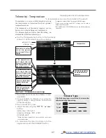
Page 97: ...which is flying can be displayed If it becomes higher or lower than the setting an alarm and or vibration will alert you Alert set Temperature warning 1 Tap Alarm and choose from Buzzer Voice and Inhibit 2 Choose Inhibit for Vibrator if not using the vibrator alarm If using vibrator choose one of the three types 3 Tap to the Limit item 4 Adjust the rate using the buttons Initial value 100 0 Adjust...

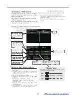
Page 98: ...g Telemetry RPM Sensor Displaying data from the rpm The RPM Sensor screen is used to set up an optional rpm sensor and display the rotation information it transmits The rotation of the model engine motor etc which is flying can be shown If it becomes higher or lower than the setting an alarm and or vibration will alert you Alarm set Over Under rotations 1 Tap Alarm and choose from Buzzer Voice and...

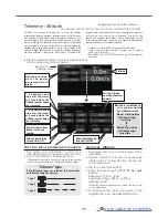
Page 99: ...ude which changed from there Even if the altitude of an airfield is high that shall be 0 m and the altitude difference from an airfield is displayed This sensor calculates the altitude from atmospheric pressure Atmospheric pressure will get lower as you go up in altitude Using this the sensor will estimate the altitude Please understand that an exact advanced display cannot be performed if atmosph...

Page 100: ...ght An altitude sensor or GPS sensor must be installed in the aircraft Telemetry Altitude Variometer Displaying data from the variometer VARIO is a screen which displays sets up the variometer information from an optional altitude sensor or GPS sensor The variometer of the model which is flying can be known If it becomes higher or lower than the setting an alarm and or vibration will alert you To ...

Page 101: ...m s W h e n t h e v a r i o m e t e r i s greater than this value Vario melody is not output Setting range 50 m s 0 m s Initial value 0 0 m s When the variometer is less than this value Vario melody is not variable Setting range 50 m s Offset value Initial value 5 0 m s When the variometer is greater than this value Vario melody is not variable Setting range Offset value 50 m s Initial value 5 0 m...

Page 102: ... is a minimum time of Vario melody output Setting range 0 0 s 0 5 s 1 0 s 1 5 s Initial value 0 0 s This parameter is effective to all variometers Delay Actually Variometer 0 0m s 1 0m s 3 0m s 4 0m s 1 0m s 2 0m s Output Vario Melody Delay time 1 0s 0 0m s 1 0m s 3 0m s 4 0m s 1 0m s 2 0m s Vario Melody Delay ...

Page 103: ...rive battery 1 EXT Battery Receiver battery Receiver battery Drive battery 2 EXT Battery Drive battery 1 EXT Battery Drive battery 2 EXT Battery Switch Power supplies for servos Another power supply Hub S BUS2 servos Two drive batteries are measured R7108SB use Twodrivebatteriesandpowersuppliesforservosaremeasured R7108SBuse Battery voltage measurement for receivers R7108SB use The drive battery 1...

Page 104: ...Allows Speech to be turned ON or OFF Tap the Voltage button in the Telemetry screen to call the setup screen shown below Max and min values s i n c e t h e p o w e r was turned ON will display Type 1 Type 2 Type 3 Vibrator type If the following types are selected the transmitter will vibrate during the warning Displaying data from the EXT battery voltage port In this screen the EXT battery voltage...

Page 105: ... ON will display It cannot be used in FASST mode and S FHSS mode Only receiver voltage and EXT voltage can be used in FASSTest12CH mode The FASSTest18CH T FHSS mode can use all the telemetry functions Distance Alarm is chosen from Buzzer Voice and Inhibit Allows Speech to be turned ON or OFF An upward arrow indicates the alarm will sound when the d i s t a n c e r e a c h e s above your set value ...

Page 106: ...a too far alarm distance 1 Tap Alarm and choose from Buzzer Voice and Inhibit 2 Choose Inhibit for Vibrator if not using the vibrator alarm If using vibrator choose one of the three types 3 Tap Limit m 4 Adjust the rate using the buttons Initial value 1 000 m Adjustment range 0 m 3 000 m Limit Limit When the screen is tapped for one second the rate is reset to the initial value 5 To terminate the ...

Page 107: ...e an aircraft that stalls at 50km h will stall if the tailwind is 5km h or greater even through 55km h is displayed by ground speed In addition with an aircraft that will disintegrate in midflight at 400km h at an over speed alarm when the headwind reaches 30km h the airplane will disintegrate in midair due to over speeding even at a ground speed of 370km h Sets the speed on which the alarm operat...

Page 108: ...iometer The GPS sensor is necessary and is sold separately Mount and connect the sensor in accordance with the sensor instruction manual It cannot be used in FASST mode and S FHSS mode Only receiver voltage and EXT voltage can be used in FASSTest12CH mode The FASSTest18CH T FHSS mode can use all the telemetry functions Max and min values s i n c e t h e p o w e r was turned ON will display Altitud...

Page 109: ...itter Servo sensor must be installed in the aircraft Select Servo sensor in the Telemetry screen and access the setup screen shown below Max and min values s i n c e t h e p o w e r was turned ON will display Sets the current on which the alarm operates Alarm is chosen from Buzzer Voice and Inhibit Allows Speech to be turned ON or OFF Vibrator is choices are type1 3 and Inhibit An upward arrow ind...

Page 110: ...s the alarm will sound when the angle reaches above your set value A downward arrow indicates the alarm will sound when the temperature reaches below your set value A downward arrow indicates the alarm will sound when the angle reaches below your set value Initial value 180 0 180 0 Adjustment range 180 0 180 0 Limit Limit Telemetry Servo sensor Temperature Angle Servo sensor must be installed in t...

Page 111: ...m Tapping this will take you to the settings screen for the voltage alarm Tapping this will take you to the settings screen for the consumption capacity alarm An upward arrow indicates the alarm will sound when the current reaches above your set value A downward arrow indicates the alarm will sound when the current reaches below your set value Type 1 Type 2 Type 3 Vibrator type If the following ty...

Page 112: ...eset to the initial value 5 To terminate the input and return to the original state push the HOME EXIT button Sets the speed on which the alarm operates Tap the Speed sensor button in the Telemetry screen to call the setup screen shown below Max and min values s i n c e t h e p o w e r was turned ON will display Speed Alarm is chosen from Buzzer Voice and Inhibit Allows Speech to be turned ON or O...

Page 113: ...34 FLI 00001234 FLD Extension FLI Slot allocation information file Extension FLD Log data file When copying or moving a log file always select both the FLI file and FLD file Log files can be converted to CSV format by using the telemetry log converter available at the Futaba website Notes Altimeter altitude data and GPS distance and altitude data output with the point that time logging started as ...

Page 114: ... ON e g Repeat time is 8 seconds and Duration time is 5 seconds Duration and Repeat time for Telemetry Alarm Tap the Telemetry Setting button in the Linkage menu to call the setup screen shown below Duration It is an alarm output time Setting range 1 s 30 s Initial value INH Duration value has to be less than repeat value Duration time is extended when the other alarm event occurs Repeat It is a r...

Page 115: ...nnel of input data from student s transmitter in the FUNC or MIX mode 2 When the T16IZ is used as the instructor s transmitter set the modulation mode of the student s transmitter to PPM If being used as the student T16IZ can be connected to the instructor s transmitter which requires the student s mode to be PPM T16IZ always sends PPM mode signal from the trainer jack In the case of student s tra...

Page 116: ...cted the trainer function is alternately turned on and off each time the switch is operated This allows alternate ON OFF switching even when a momentary switch SH is used Note The trainer function won t be turned on unless the Instructor s transmitter receives signals from the student s transmitter Be sure to confirm this after connecting your trainer cable When using at the student side 1 Select ...

Page 117: ...he switch which enables student side operation can be selected See Switch selection method at the end of this manual for selection method details Trainer student channel setting function In training mode the instructor s transmitter can pick up the student s signal on both the Function and Mix channels That makes it easy for the two transmitters to connect even if the student and instructor have s...

Page 118: ...tting button in the Linkage menu to call the setup screen shown below The settings can be changed individually When set to Inhibit a warning is not displayed at power ON Type 1 Type 2 Type 3 Vibrator type If the following types are selected the transmitter will vibrate during the warning Return to Linkage menu WARNING It is extremely dangerous to unnecessarily inhibit essential warnings Careless s...

Page 119: ...l method of use are the same Changes made in either way are saved into the transmitter memory User menu setting Original menu screen making Tap the User menu setting button in the Linkage menu to call the setup screen shown below Tap here to select your first choice Once pressed 3 pages of choices will be displayed Make your selection press your choice and the first of your User menu will be enter...

Page 120: ... setting Function Name A function name is reset Telemetry Reset the telemetry setting Trim All condition Resets only the Trim all conditions Trim Current and Group condition Resets only the data of Trim condition in use and all the conditions set to group mode Model menu setting Resets all the functions in the model menu except the condition selection functions All model setting Resets all the fun...

Page 121: ...e flap This mix operates the brake flaps in the aileron mode It improves the operation characteristic of the roll axis Airplane glider 4 flaps or more Aileron Rudder This mix is used when you want to operate the rudder at aileron operation Banking at a shallow bank angle is possible Airplane glider general Elevator Camber This mix is used when you want to the mix camber flaps with elevator operati...

Page 122: ...ated function changes after a delay corresponding to the set amount When multiple conditions were set their operation priority can be freely changed The condition name can be changed The selected condition name is displayed on the screen When a condition has been added give it a name which can be easily confirmed Conditions List Select Condition select at the model menu and call the setup screen s...

Page 123: ...apped the condition is reset To abort resetting tap the No button Priority change 1 Tap the condition whose priority you want to change in Conditions List 2 Change the priority with the priority or button The last condition has the highest priority The initial setting condition cannot be moved It has the lowest priority Last condition has the highest priority Condition delay setting 1 Switch to th...

Page 124: ...on when the function is operated including at flight condition switching can be adjusted The function operates smoothly at a constant speed corresponding to the set speed Select AFR at the model menu and call the setup screen shown below Function selection 1 When the function select button is tapped a selection screen appears 2 Select the function you want to set at the selection screen When D R i...

Page 125: ...er conditions D R at the top of the D R list has priority The ON OFF switch of dual rate is chosen Activate the D R function by tapping the INH When the function select button is tapped a selection screen appears Select the function you want to set at the selection screen Setting rudder angle EXP On this D R screen you can set functions and switchover switches Rudder angle rate and EXP settings ar...

Page 126: ...ration and may control up to four circuits simultaneously The Programmable mixing includes a powerful link function which allows Programmable mixing to be linked with the special mixing functions or with other programmable mixing functions The link function can be set up for Master and Slave channel individually Fine tuning trim setting The on time start stop time can be set up to 4 seconds It is ...

Page 127: ... by tapping the Stick Switch Dial button and then select master channel side control Slave channel setting 1 Tap the Slave button to call the Function menu and select the slave channel 2 To link this mixing with other mixing tap the Link button Each time the button is pressed it toggles between mixing direction and and OFF no link Trim mode ON OFF setting 1 To turn the trim mode ON OFF tap the Tri...

Page 128: ...ron angles When setting the fine tuning VR tap the item and tap the screen to call the selection screen and then select the fine tuning VR The fine tuning rate can be set by curve Select Aileron differential at the model menu and call the setup screen shown below Condition group single mode selection Gr Sngl For more information see the description at the back of this manual Currently selected con...

Page 129: ...een ON is displayed When setting a switch tap the item of the switch and tap the screen to call the selection screen Then select the switch and set its ON direction Always ON at setting For a description of the switch selection method see the description at the back of this manual Camber flap setting Brake flap setting Select Flap setting at the model menu and call the setup screen shown below The...

Page 130: ...screen and then select the switch and set its ON direction Always ON at setting For a description of the switch selection method see the the back of this manual Tap the left or right item of each flap servo Adjust the mixing rate When the mixing direction is reversed by the linkage adjustments can be made by changing the mixing rate polarity or A mixing curve can be set 1 2 page For a description ...

Page 131: ...ion screen and then select the switch and set its ON direction Always ON at setting For a description of the switch selection method see the at the back of this manual Tap the left or right button of each flap servo Adjust the mixing rate When the mixing direction is reversed by the linkage adjustments can be made by reversing the mixing rate polarity or A mixing curve can be set For a description...

Page 132: ...select the VR The adjustment rate can be set The VR operation mode can also be selected A mixing curve can be set For a description of the curve setting Fine tuning VR operation mode LIN Mixing rate 0 at center of VR When the VR is turned clockwise and counterclockwise the mixing rate increases and decreases respectively ATL Mixing rate 0 at left end of VR When the VR is turned the mixing rate inc...

Page 133: ...ription of the switch selection method see the description at the back of this manual When setting a VR tap the Fine tuning item and tap the screen to call the selection screen and then select the VR The adjustment rate can be set The VR operation mode can also be selected A mixing curve can also be set For a description of the curve setting method see the description at the back of this manual Se...

Page 134: ... independently by curve and attitude changes caused by camber operation can be corrected Initial setting assigns camber operation to side lever LS The up down side rates of the aileron flap and elevator servos can be adjusted by curve When the mixing direction is reversed by the linkage adjustments can be made by changing the mixing rate polarity or Mixing during flight can be turned ON OFF by set...

Page 135: ... the description at the back of this manual When setting a condition delay tap to the Condition delay item Set the delay When setting a cut switch tap Cut switch and tap the screen to call the selection screen and then select the switch and set its ON direction Always ON at setting For a description of the condition delay function see the description at the back of this manual Curve rate setup scr...

Page 136: ...tly selected condition name Mixing curve setting For a description of the setting method see the description at the back of this manual Up Down overall adjustment at Rate A and Rate B Activate the function by tapping the INH Condition group single mode selection Gr Sngl The ON OFF switch of mixing is chosen Fine tuning setting Setting method Tap INH ON is displayed When setting a switch tap the it...

Page 137: ...e made by changing the mixing rate polarity or A mixing curve can be set Mixing during flight can be turned ON OFF by setting a switch Always ON at setting The mixing rate can be fine tuned by setting a VR Setting method Tap INH ON is displayed When setting a switch tap to the item of the switch and tap the screen to call the selection screen Then select the switch and set its ON direction Always ...

Page 138: ...en Then select the switch and set its ON direction Always ON at setting For a description of the switch selection method see back of this manual When setting a VR tap to the Fine tuning item and tap the screen to call the selection screen and then select the VR The adjustment rate can be set The VR operation mode can also be set For a description of the fine tuning VR setting method see the descri...

Page 139: ...N is displayed Currently selected condition name Mixing curve setting For a description of the setting method see the description at the back of this manual Up Down overall adjustment at Rate A and Rate B Activate the function by tapping the INH Condition group single mode selection Gr Sngl The ON OFF switch of mixing is chosen Fine tuning setting To set linking tap to the OFF item Rudder Elevator...

Page 140: ...ay can be set for each condition A cut switch which can turn OFF the delay function can also be set The differential rate can be adjusted When servo binding occurs when setting the ailerons and flaps in butterfly mixing use the AFR function to adjust the rate Select Butterfly at the model menu and call the setup screen shown below The display screen is an example The actual screen depends on the m...

Page 141: ...ion rate setup screen Overall adjustment by Rate A and Rate B Mixing curve setting For a description of the curve setting method see the description at the back of this manual Elevator rate adjustment Select the Mixing Rate AIL and FLP box Adjust the mixing rates Return to Model menu The offset position is indicated by a red dotted line by an elevator curve To elevator curve setup screen Fine tuni...

Page 142: ...terfly motion is not reversed Mode A Normal The butterfly operation direction is reversed at the neutral position 50 of the throttle stick Throttle stick full stroke MODE Mode B Throttle stick full stroke MODE It does not reverse at the neutral position so you can set the butterfly operation start point with the full stroke of the throttle stick ...

Page 143: ...ON OFF switch 3 Select the Manual or Auto mode In the Auto mode also select an auto SW This switch can be linked to a stick etc Speed In The operation speed at switch ON can be set Out The return speed at switch OFF can be set Fine Tuning The offset rate can be varied in the Fine Tuning numeric range set at screen by VR etc selection Condition Delay When flight conditions are set the operation spe...

Page 144: ...peed of the aileron elevator and flap servos can be adjusted for each snap roll direction In side out side Example Setting example for F3A Mode Master Safety SW SW G Safety measure Master SW SW H Main switch for executing snap roll Direction switches The snap roll up side left and right and down side left and right direction switches are selected here Right Up SW D OFF OFF ON Right Down SW D ON OF...

Page 145: ...leron 1 Aileron 2 Elevator Air brake This function is used when an air brake is necessary when landing or diving etc The preset elevators and flaps camber flap brake flap offset amount can be activated by a switch The offset amount of the aileron elevator and flap servos can be adjusted as needed Also the speed of the aileron elevator and flap servos can be adjusted In side Out side A delay can be...

Page 146: ... item Adjust the rate When using this function Tap INH When a Futaba GYA gyro is used when GY type is selected the sensitivity set value is directly read in both the AVCS and Normal modes When setting a switch tap the Switch item and tap the button to call the selection screen and then select the switch and set its ON direction For a description of the switch selection method see the description a...

Page 147: ...et so that Rate 1 is turned on at the back position of switch E and Rate 3 is turned ON at the front position Since switch E is turned OFF at the center Rate 2 remains INH Rudder servo Elevator servo Aileron servo S BUS2 port S BUS Receiver GYA451 GYA451 GYA450 GAIN 0 AVCS NORMAL When AVCS is used we recommend that the sensitivity CH be set to the 3 position Rate ACT Type Switch Gyro Gyro 2 Gyro 3...

Page 148: ...y on larger wingspan planes Note Select ailevator as the Model type at the Model type screen This changes the output channel Check the Function menu Select Ailevator at the model menu and call the setup screen shown below Travel adjustment Tap to the item you want to adjust Adjust the rate using the buttons If the mixing direction is reversed by the linkage adjustments can be made by changing the ...

Page 149: ...is not performed when Ele to camber mixing is INH The acceleration function can be set for both the up side and down side Function ON OFF switch setting is performed for Aileron Rudder setting only Aileron Rudder setting is acceleration function setting for Aileron Rudder mixing It is not performed when Aileron Rudder mixing is INH Note When using the acceleration function since the servo stroke i...

Page 150: ...menu Note When using this function always check initial operation with the propeller removed When using this function Tap INH When you want to set the One time mode tap to the One time item and tap the screen Speed 1 to 2 The speed 1 and speed 2 region boundary can be changed Operation speed adjustment The speed when speed 1 and speed 2 are ON In and OFF Out can be adjusted When using this functio...

Page 151: ... as they can serve the same purpose Rudder function Left and right travel adjustment at CH1 and CH2 rudder operation Elevator function Up and down travel adjustment at CH1 and CH2 elevator operation Select V Tail at the model menu and call the setup screen shown below Travel adjustment Tap to the item you want to adjust Adjust the rate using the buttons If the mixing direction is reversed by the l...

Page 152: ...o mounted rudder servos can be adjusted separately Two servos are operated with one rudder stick Rudder 1 2 The travel at rudder stick left and right operation can be individually set Select Winglet at the model menu and call the setup screen shown below Travel adjustment Tap to the item you want to adjust Adjust the rate using the buttons If the mixing direction is reversed by the linkage adjustm...

Page 153: ...n Condition hold will display ON and an alarm will sound WARNING For safety reasons when performing individual adjustments it is recommended that you shut off the engine and disconnect the motor to prevent rotation Sudden abrupt rotation can result in death or serious injury MODEL MENU Helicopter functions Model menu Helicopter functions table Servo monitor Displays the servo test and operation po...

Page 154: ...ated function changes after a delay corresponding to the set amount When multiple conditions were set their operation priority can be freely changed The condition name can be changed The selected condition name is displayed on the screen When a condition has been added give it a name which can be easily confirmed Conditions List Select Condition select at the model menu and call the setup screen s...

Page 155: ...apped the condition is reset To abort resetting tap the No button Priority change 1 Tap the condition whose priority you want to change in Conditions List 2 Change the priority with the priority or button The last condition has the highest priority The initial setting condition cannot be moved It has the lowest priority Last condition has the highest priority Condition delay setting 1 Switch to th...

Page 156: ...h function when the function is operated including at flight condition switching can be adjusted The function operates smoothly at a constant speed corresponding to the set speed Select AFR at the model menu and call the setup screen shown below Function selection 1 When the function select button is tapped a selection screen appears 2 Select the function you want to set at the selection screen Wh...

Page 157: ... other conditions D R at the top of the D R list has priority The ON OFF switch of dual rate is chosen Activate the D R function by tapping the INH When the function select button is tapped a selection screen appears Select the function you want to set at the selection screen Setting rudder angle EXP On this D R screen you can set functions and switchover switches Rudder angle rate and EXP setting...

Page 158: ...ration and may control up to four circuits simultaneously The Programmable mixing includes a powerful link function which allows Programmable mixing to be linked with the special mixing functions or with other programmable mixing functions The link function can be set up for Master and Slave channel individually Fine tuning trim setting The on time start stop time can be set up to 4 seconds It is ...

Page 159: ... by tapping the Stick Switch Dial button and then select master channel side control Slave channel setting 1 Tap the Slave button to call the Function menu and select the slave channel 2 To link this mixing with other mixing tap the Link button Each time the button is pressed it toggles between mixing direction and and OFF no link Trim mode ON OFF setting 1 To turn the trim mode ON OFF tap the Tri...

Page 160: ...ring Use this function together with the THR curve normal function and adjust the curve so that up down control is best at a constant engine speed Idle up curve adjustment For the high side pitch curve set the maximum pitch which does overload the engine For the low side pitch curve create curves matched to loop roll 3D and other purposes and use the idle up curves according to the performance Thr...

Page 161: ...ently select the single mode initial setting Other conditions can be set independently Setting method The screens shown below are curves created by entering the pitch rate at low center and high side 3 points or 5 points at each condition When actually creating a curve input the rate specified at the fuselage or the reference value For a description of the curve setting method see the description ...

Page 162: ...H ON is displayed Select the adjustment knob Selection example LD The trim operation mode Mode Center Normal can be selected Center mode Maximum amount of change near center by center trim operation recommended Normal mode Normal trim parallel movement trim operation The advantage of using this mode is that the hovering pitch can be adjusted without changing the curve Trim adjustment range Range s...

Page 163: ... the pitch performed in flight Create a curve matched to loop roll 3D or other purposes and the idle up curve according to the performance Operation precautions WARNING When actually starting the engine and flying always set the idle up condition switch to OFF and start the engine in the idling mode Setting method Group single item When you want to simultaneously enter the same settings to other f...

Page 164: ...tor speed accompanying changes in the temperature humidity and other flight conditions can be trimmed Adjust the throttle so that rotor rotation is most stable More delicate trimming is also possible by using this function along with the Hover Pitch function Setting method When using the hovering normal condition only switch the group mode to the single mode initial setting and make the settings T...

Page 165: ... low The operation point is displayed on a graph Acceleration rate setting Rate The return time after operation Damping can be set Acceleration Select Acceleration at the model menu and call the setup screen shown below Operation up to this range will initiate acceleration Act position The rate the angle increases To next page 1 2 Pitch 2 2 Throttle The return time after operation Damping can be s...

Page 166: ...nked to the throttle stick position Auto position setting When the auto mode is selected the throttle position auto position can be selected Move the throttle stick to the position you want to set and tap the screen Auto position is displayed Hold position adjustment Throttle Hold Cut sets the throttle cut position Adjust it so that the carburetor is fully closed Throttle Hold Idle Make this adjus...

Page 167: ...and the right aileron is operated the elevator moves to the down side Tune by adjusting the Rate For right roll adjust to the rate A side Setting method When using this function Tap INH ON is displayed When you want to set the same contents at other conditions select the group mode When you want to set the selected condition only select the single mode initial setting The correction rate can be se...

Page 168: ...t to set the selected condition only select the single mode initial setting The correction rate can be set by curve A switch can be set When is set the swash mixing function is operated by merely selecting the condition When setting an ON OFF switch tap to the item and tap the screen to call the selection screen and set the switch and its ON position When correction is necessary tap to the mixing ...

Page 169: ... the selection screen and set the switch and its ON position Acceleration function setting A c c e l e r a t i o n c a n b e s e t a t b o t h acceleration high and deceleration low The acceleration rate rate and the return time after operation damping can be set An operation point Act position at acceleration and deceleration can be set When an operation point was exceeded acceleration operation ...

Page 170: ...our own rhythm and adjust the pitch so the nose does not deflect when the throttle is raised and lowered 2 Throttle high side climbing and diving from hovering Repeat climbing and diving from hovering at a constant rate matched to your own rhythm and adjust the pitch so that the nose does not deflect when the throttle is raised and lowered However when a GY Series or other heading hold gyro is use...

Page 171: ...nction is used to adjust gyro sensitivity The sensitivity and operation mode Normal mode AVCS mode can be set for each condition The gyro sensitivity can be switched with each condition or the switch 3 sensitivities Compatible with 3 axis gyro CGY750 Setting method When using this function Tap INH ON is displayed When you want to set the same contents at other conditions select the group mode When...

Page 172: ... idleup perform switchover for each condition and adjust sensitivity Because sensitivity changes for hovering and idleup perform switchover for each condition and adjust sensitivity Because the sensitivity is switched Sngl per condition Rate 2 and Rate 3 are not used Because the sensitivity is switched Sngl per condition Rate 2 and Rate 3 are not used Tapping here will let you select either Normal...

Page 173: ...s set Control and Trim to for Governor and Governor 2 of the Function menu of the Linkage menu Select Governor at the model menu and call the setup screen shown below Fine tuning VR settings RPM adjustment Unit display selection rpm Setting method Activate the mixing When using this function Tap INH ON is displayed When the function is set ON OFF at the governor setup screen the governor rpm setti...

Page 174: ...d on screen The chart below indicates the mode percentage and the corresponding RPM main rotor R P M 3900rpm 2700rpm 2100rpm 0 100 110 main rotor R P M setting channel travel 50 neutral 2500rpm 2000rpm 1500rpm 1000rpm 700rpm 3500rpm Fine tuning VR settings Tap to the item and tap the screen to access the selection screen Select the control For a description of the switch selection method see the d...

Page 175: ...une aileron HeadResp Head Response HeadHld E Head hold elevator StopTune E Stop tune elevator Rudder Expert EXP AVCS Rudder exponential AVCS EXP NORM Rudder exponential NORMAL CNT DlIn Control delay in CNT DlOut Control delay out ANG Pirouette speed Tail Resp Tail response A Wired connection Advanced settings all functions same as GPB 1 T16IZ S I F P BOX CGY Connection Cable included with gyro CGY...

Page 176: ...ears 1 3 2 SETTING CAUTION Be sure to connect and disconnect the CGY760R CGY755 and T16IZ connection cable with the power off When copying data from Gyro A to Gyro B Connect the gyro A to the T16IZ and press Start Enter the data of A into T16IZ Connect Gyro B to T16IZ and press GY Settings Transfer Put data on A into gyro B Select Start This will download the gyro data to the T16IZ When GY Setting...

Page 177: ...nother gyro you need to reconnect the cable and download the data First wired connection Next Wireless tunings 2 Select Start This will download the gyro data to the T16IZ 1 2 SETTING T16IZ S I F P BOX CGY755 CGY760R 1 3 Select Wireless Tuning 3 2 4 Items that can be set wirelessly are displayed 4 1 Select Gyro setting on the last page of Helicopter Model Menu 2 Select Start CGY Connection Cable i...

Page 178: ...available Function Menu of your transmitter DG1 Assigning DG1 to a switch or flight mode allows the use of two separate values for the condition selectable parameters If you set a condition switch channel using the AFR function on that channel set a flat point curve for each flight condition Then you can utilize all 5 flights conditions Set the point curve with AFR for each flight condition of the...

Page 179: ...ceiver screen Basic menu screen Flight Tune Aileron Elevator Swash Basic Swash Rud Basic Rudder Gov Basic Governor S BUS Basic Swash Detail Swash Flight Tune Expert Aileron Rudder Expert Rudder Governor Expert Governor Internal Rx RF type Home Screen Home Screen ...

Page 180: ...Menu Basic Menu As the name suggests this menu allows changes to the basic settings of CGY Make sure to set each BASIC MENU Basic menu screen Flight Tune Aileron Elevator Swash Basic Swash Rud Basic Rudder Gov Basic Governor S BUS Basic ...

Page 181: ...e In that case select all swash servo types in SWH basic servo type Setting AN 70Hz DG 760μS DG 285Hz Initial setting DG 285Hz WARNING The servo type parameter within the CGY must match the type of servo you are using Incorrect setting may damage the CGY or the servo Incorrect setting may also result in a loss of control during flight S BUS connection Condition on change channel Using the methodol...

Page 182: ...rameters which are good for not only 3D but also F3C flying F3C Mode and L SCALE Large scale model Mode are for unique or special tuning types only When the style is changed setting of AIL ELE RUD is re initialized and defaults are changed L SCALE Initial parameter mode corresponding to a large machine with a total length of 2 5m or more 2 Gyro Set Dir Mounting direction Set the roll axis pitch ax...

Page 183: ... transmitter should be set to H 1 or single servo mode All CCPM mixing is set up and handled in the CGY and the transmit ter functions should not be used Before starting model set up be sure that all dual rates pitch curve and endpoint values are set to 100 100 5 Servo Dir Servo direction Using different servo combinations will create the proper swash plate servo movement in electronic CCPM models...

Page 184: ...e CGY roll pitch axis will compensate when the helicopter rolls pitches Pick the helicopter up and roll the helicopter to the right The CGY should compensate by add ing left cyclic to the swash plate Pick the helicopter up and rotate the nose of the helicopter downward The CGY should compensate by adding aft cyclic to the swash plate If the CGY compensates in the wrong direction then it will be ne...

Page 185: ...eter saves the zero collective pitch point into the CGY Setting method Touch the Pit Zero rate button to enter the setting mode Operate the throttle stick to 0 degree pitch Touch the Pit Zero rate button again Sure Is displayed If you touch the Yes button The zero pitch signal will be saved to the CGY 16 Pit Low Pitch low memorizing This parameter saves the full negative collective pitch point int...

Page 186: ...nd 1 Base Gain Gyro base gain setting This sets the Cyclic Gyro Base Gain If the Rotor Head Gain Rot HD Gn Channels are set to INH within the CGY SBUS BASIC menu then the remote transmitter gain adjustment is not available Thus the actual work ing gain for the cyclic gyros is set by using the Base Gain button within this parameter Set to 100 a transmitter Gain value of 100 will display 100 on this...

Page 187: ... a lower value will reach the desired CYC Rt slower and accelerate slower to the desired angular rate Note Setting this value too high could lead to a jerky feeling when mak ing rapid stick corrections a value too low will give you the impression the model is not following the pilot s stick inputs Values of between 20 60 are the suggested range for most helicopters Setting ranges 0 100 Initial val...

Page 188: ...3D rotor blades this function is not needed If you do notice a slight tendency for the nose to try to rise or fall with collective input in creasing ELE Comp will reduce this behavior Setting ranges 0 100 Initial value 0 8 HP Auth High pitch authority When a rotor blades angle of attack is increased the rotor blade becomes less reactive in turn the helicopter might not feel as reactive at high pit...

Page 189: ...tting value Normal Reverse Initial value Normal 3 Work Mode Gyro working mode The available choices are CMT Normal or AVCS The CMT mode will allow you to select either AVCS or Normal mode via the transmitter In Normal mode the gyro will always operate in Normal Rate Mode and when AVCS is selected it will always operate in AVCS Mode Setting CMT Normal AVCS Initial setting CMT 4 GY Gain Gyro base ga...

Page 190: ... gear N2 Gear ratio N1 N2 Carry values less than 1 1000 to the next whole number 3 Pole Num Pole number This parameter is used when using a direct phase sensor attachment to a brushless motor lead Input the motor pole count as specified by the brush less motor manufacturer When using any revolution sensor other than a direct phase sensor type set the pole number to 2p Note For nitro use set to 2p ...

Page 191: ...en Battery Fail Safe is enabled items for setting the throttle servo posi tion are displayed The setting method is the same as Stick sw so please refer to this section of the manual for information on setting this function 8 BAT F S Battery fail safe When the receiver battery voltage becomes equal to or less than BFS Volt set in the Governor Expert menu the battery fail safe function is ac tivated...

Page 192: ...2 rpm out RPM display on transmitter When displaying the rpm with the telemetry function set it to ACT Setting ACT Active INH Inhibit Initial setting INH 15 SBUS2 rpm Slot RPM display on transmitter Set the slot number of the telemetry rotation sensor registered on the transmitter side This must be set so that no slots overlap one another 16 Rev Sensor Revolution sensor testing This menu is utiliz...

Page 193: ...CONTENTS Expert Menu Expert Menu This menu enables the user to further refine the gyro and governor settings Expert Menu Swash Detail Swash Flight Tune Expert Aileron Elevator Rudder Expert Rudder Governor Expert Governor ...

Page 194: ...r pushrod prior to making adjustments with this parameter Setting ranges 240 0 240 Initial value 0 2 EXP AVCS EXP NORM Rudder exponential This parameter sets the feel of the tail rotor control around center When set to 0 the control curve is linear Using a value the tail rotor will be more sensitive around neutral conversely using a value will soften the feeling around neutral The RUD EXP paramete...

Page 195: ...ing mode and set the delay amount Do the same for the other side Setting ranges 0 20n Initial value 15n 4 CNT DlOut Control delay out This parameter sets the delay when the stick is returned back to the neu tral position This parameter is useful to tune how aggressively the tail rotor stops following a pirouette The higher the value the softer the stop This parameter must be adjusted individually ...

Page 196: ... after to help cure the sudden change in torque but it does not allow the large tail rotor input to alter the axial behavior of the helicopter Setting ranges 0 200 Initial value 0 8 Tail Resp Tail response The goal is to match the response between the helicopter tail response and the gyro control This feature is utilized to do so 1 is the fastest response Gener ally if the tail response is slow or...

Page 197: ...unces on the aileron axis after an aileron control input increasing StpTune A will reduce this bounce Setting ranges 0 250 Initial value 80 3 StopTune E Stop tune elevator Cyclic stop tuning on the elevator axis If the helicopter after an elevator flip continues to coast lowering StopTune E will create a harder stop action to remove the coasting If the helicopter continues to coast after an elevat...

Page 198: ...eter adjusts the pitch to 2nd elevator mixing rate The rates can both be adjusted individually for both full high and low collective positions Note This setting is only available if the H4 xx swash mode has been selected Setting ranges 30 150 Initial value 100 4 AIL PIT aileron collective pitch mixing rate At the middle collective pitch check that during right to left and left to right aileron act...

Page 199: ...e used when H4 00 swash mode is selected Setting ranges 30 150 Initial value H3 120 50 except H3 120 100 9 ELE ELE2 elevator 2nd elevator mixing rate This parameter adjusts the elevator to 2nd elevator mixing rate The rate can be adjusted separately for up and down directions individually Note This setting is only available if the H4 xx swash mode has been selected Setting ranges 30 150 Initial va...

Page 200: ...a tor input Having previously set the ELE PIT and ELE AIL parameters if during rapid movement of the elevator axis the swash plate is not staying level use the Speed Comp button to match all servo speeds Note a will slow the Aileron Pitch Servo will reduce speed comp on Aileron Pitch Servo Setting ranges 0 100 Initial value H3 120 50 except H3 120 0 15 SWASH Rot Swash rotation Using the SWASH Rot ...

Page 201: ...e setting on the transmitter Fixed This is the suggested mode for use with electric motors This setting ensures that there is a fixed throttle input as is related to the helicopter revolution Tx Curve If this mode is selected the CGY uses the exact throttle input from the transmit ter As such the throttle curve setting on the transmitter is required Note when the Rev Lmt mode is selected this mode...

Page 202: ...come active The default value is 60 In this case the governor will not engage until the engine rpm reaches 60 of the set rpm If you feel that the time for governor engagement is too slow decrease the value to 50 55 The starting time will be faster Setting ranges 50 90 Initial value 60 10 BFS Volt Battery F S voltage setting This parameter sets the battery fail safe and low battery alarm voltage le...

Page 203: ...light conditions Up to 8 conditions can be used MODEL MENU Multicopter functions Model menu Multicopter functions table Servo monitor Displays the servo test and operation position Condition select Flight conditions addition deletion copy condition renaming and condition delay can be set AFR Sets the angle and curve of all the operation functions Dual rate D R curve which can be switched with a sw...

Page 204: ...ated function changes after a delay corresponding to the set amount When multiple conditions were set their operation priority can be freely changed The condition name can be changed The selected condition name is displayed on the screen When a condition has been added give it a name which can be easily confirmed Conditions List Select Condition select at the model menu and call the setup screen s...

Page 205: ...apped the condition is reset To abort resetting tap the No button Priority change 1 Tap the condition whose priority you want to change in Conditions List 2 Change the priority with the priority or button The last condition has the highest priority The initial setting condition cannot be moved It has the lowest priority Last condition has the highest priority Condition delay setting 1 Switch to th...

Page 206: ...h function when the function is operated including at flight condition switching can be adjusted The function operates smoothly at a constant speed corresponding to the set speed Select AFR at the model menu and call the setup screen shown below Function selection 1 When the function select button is tapped a selection screen appears 2 Select the function you want to set at the selection screen Wh...

Page 207: ... other conditions D R at the top of the D R list has priority The ON OFF switch of dual rate is chosen Activate the D R function by tapping the INH When the function select button is tapped a selection screen appears Select the function you want to set at the selection screen Setting rudder angle EXP On this D R screen you can set functions and switchover switches Rudder angle rate and EXP setting...

Page 208: ...ration and may control up to four circuits simultaneously The Programmable mixing includes a powerful link function which allows Programmable mixing to be linked with the special mixing functions or with other programmable mixing functions The link function can be set up for Master and Slave channel individually Fine tuning trim setting The on time start stop time can be set up to 4 seconds It is ...

Page 209: ... by tapping the Stick Switch Dial button and then select master channel side control Slave channel setting 1 Tap the Slave button to call the Function menu and select the slave channel 2 To link this mixing with other mixing tap the Link button Each time the button is pressed it toggles between mixing direction and and OFF no link Trim mode ON OFF setting 1 To turn the trim mode ON OFF tap the Tri...

Page 210: ...using this function Tap INH When a Futaba GY gyro is used when GY type is selected the sensitivity set value is directly read in both the AVCS and Normal modes When setting a switch tap the Switch item and tap the button to call the selection screen and then select the switch and set its ON direction For a description of the switch selection method see the description at the end of this manual Sel...

Page 211: ...me between channels can be suppressed by using the condition delay function of the condition select function Condition select When the delay function is set at the switching destination condition a delay corresponding to that amount is applied and the related functions change smoothly Setting method 1 Switch to the condition you want to set and tap the delay 0 value 2 Set the delay using the butto...

Page 212: ...the neutral position the mixing rate increases Setting method 1 Control selection Tap the Control button to call the Hardware select screen and then select the switch and its ON direction 2 Mode selection Tap the Mode button and then select the mode LIN ATL ATL or SYM 3 Rate adjustment Tap the Rate value button Set the rate using the buttons Initial value 0 Adjustment range 100 100 When the value ...

Page 213: ... function Symmetry mode Used with ailerons and other self neutral functions Linear mode Used with functions which hold the operation position of the throttle and switch channel etc Setting method 1 Select the mode Linear or Symmetry Each time the button is tapped it toggles between Linear and Symmetry 2 Tap the In or Out Speed button and set the servo speed Initial value 0 Setting range 0 27 First...

Page 214: ...FR function and each mixing function Curve type selection Four types of curves EXP1 EXP2 Point and Spline can be selected Curve type selection 1 Tap the button of the curve type you want to use The curve type changes and the display returns to the original screen EXP1 EXP1 curve EXP2 EXP2 curve Point point curve Spline spline curve ...

Page 215: ...XP2 curve Using the EXP2 curve is effective in engine rise and other engine control The curve left and right rates Rate A Rate B and EXP curve rate EXP A EXP B can be adjusted individually EXP for EXP2 The curve can also be offset horizontally Offset in the vertical direction Rate setting 1 Tap to the Rate A Rate B EXP A or EXP B setting item 2 Set the rate using the buttons Initial value 100 0 ra...

Page 216: ...int becomes an outlined point 3 Use the move between points button or The point is deleted 2 Tap the Position button 3 Tap the button and select the position mark you want to add 1 Use the move between points button or and select the point The red point is the selected point 4 When the Add is tapped the point is added A new point is created 5 Press Rate and use the up down arrows to adjust the rat...

Page 217: ...ncreased decreased and offset Rate adjustment of each point 2 Tap to the Rate i t e m A n d s e t t h e r a t e u s i n g the buttons Repeat steps 1 through 2 and adjust the curve Point curve Point adjustment Point Separ mode Normal setting Comb mode Creates a left and right symmetrical curve 1 Tap to the item and select the point whose rate you want to set The mark on the curve shows the currentl...

Page 218: ...ch is selected Switch ON OFF setting is possible at each position 1 When the ON OFF Set position switch is tapped after the switch was selected the screen shown below appears When the button of each position is tapped it toggles between ON and OFF 2 Tap the button and set to the ON position 3 Close the screen by tapping Hardware select When stick trim lever or VR is selected When a stick trim leve...

Page 219: ...e Reverse button The operation is the same as the linear hysteresis mode but left and right up and down operations are symmetrical about the neutral position For example when you want to switch DR1 with the aileron stick when the stick is moved to the left or right DR1 can be turned ON at the same left and right position This mode turns on the switch within a range of 2 points Each point can be se...

Page 220: ...4 Touch the Lower button The boundary points change Symmetry Symmetry When shifting the ON OFF point The ON OFF and hysteresis dead band boundary point there are 2 points top and bottom position can be shifted ON OFF is possible at a free position When Upper Lower is set at the same time Lower Upper is also set When Upper Lower is set at the same time Lower Upper is also set Hysteresis Hysteresis ...

Page 221: ...on is ON Switch mode selection 1 Tap to the Mode Single item Logic switch setting screen Switch selection 1 Select the switch A and B Logic mode selection 1 Tap to the Logic item 2 Select the logic mode Logic switch Condition select and DG1 DG2 The logic switch function lets you turn operation on and off by combining two switches For instance the condition is activated when 2 switches are turned o...

Page 222: ...n be used as a game controller 1 Connect T16IZ to your PC and start Real Flight 2 Select Settings from the Simulation menu of RealFlight to open the Settings dialog 3 Set Deadband Percentage of Controller to 0 4 Click the OK button to close the Settings dialog 5 Select Select Controller from the Simulation menu to open the Select Controller dialog 6 Set Profile to Futaba and click the Edit button ...

Page 223: ...Calibrate button to calibrate Set the stick switch dial and lever to be used in the neutral position and press the Next button 10 Operate the stick switch dial and lever fully left and right or up and down to enter the operating range After confirming that the correction is complete press the Finish button to return to the Select Controller dialog 11 Click the OK button in the Select Controller di...

Page 224: ...o be safe back up the model data before updating 1 Download the zip file of the update data from our website 2 Extract the zip file on your computer 3 The FUTABA folder will be created on your computer 4 Copy the FUTABA folder into your microSD card Note If the microSD card has already had another FUTABA folder before you make a copy the FUTABA folder is OVERWRITTEN 5 Insert the microSD card with ...

Page 225: ... error The update file may be broken or for another transmitter Write error The software update procedure is stopped for an unknown reason Contact your local service center when this error message appears on the LCD screen of your T16IZ Don t absolutely remove the battery and the microSD card from the transmitter during the update There is a possibility that the transmitter will be damaged Recover...

Page 226: ...pace in its internal memory converts must fail When microSD card cannot be recognized it may be able to be used if it reformats by SD formatter offered from SD Association SD formatter is downloadable from SD Association https www sdcard org CAUTION After finishing data copy be sure to perform a complete check of operation with the model to be used Check well all the directions of operation and al...

Page 227: ...dified copies of the Font Software subject to the following conditions 1 Neither the Font Software nor any of its individual components in Original or Modified Versions may be sold by itself 2 Original or Modified Versions of the Font Software may be bundled redistributed and or sold with any software provided that each copy contains the above copyright notice and this license These can be include...

Page 228: ......
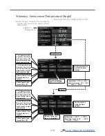
Reviews: