2-6
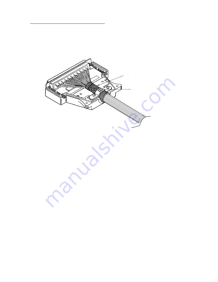
Assembling D-SUB connector (CN-A302)
1. Remove vinyl sheath of cores by 3 mm.
2. Pass the cores through shrink tubing (local supply).
3. Solder cores to connector pins referring to the interconnection diagram at the back of this
manual.
4. Assemble the connector.
Fold back shield onto cable,
and wrap with shield tape.
Cable clamp
Assembling D-sub connector
2.3.2 Connecting cable between processor unit and monitor unit
For the FURUNO-supplied monitor, connect the cable (10S2074 or 1022075) from the
processor unit (FSV-8402) to the CN-A302 – CN-A308 connectors on the monitor unit
(FSV-2400).
Attach connector from processor unit and control unit as below.
1. Unfasten four screws (M4
×
10) at the rear of the monitor to loosen the cable cover.
2. Lift and pull the cable cover to remove it.
3. Unfasten two screws (M4
×
10) to remove the clamp cover.
4. Lay the monitor and control cables on the clamp, and then reattach the clamp plate to fix
cables.
5. Connect eight connectors referring to the instruction sticker by the connector board.
6. Reattach the cable cover.
Summary of Contents for FSV-84
Page 1: ...COLOR SCANNING SONAR FSV 84 www furuno co jp ...
Page 28: ...1 20 This page intentionally left blank ...
Page 48: ...2 20 This page intentionally left blank ...
Page 76: ...A 23 ...
Page 77: ......
Page 78: ......
Page 79: ......
Page 80: ......
Page 81: ......
Page 82: ......
Page 83: ......
Page 84: ......
Page 85: ......
Page 86: ...Nov 22 06 T Matsuguchi ...
Page 87: ...Nov 22 06T Matsuguchi ...
Page 88: ......
Page 89: ...D 16 ...
Page 90: ......
Page 91: ...Mar 14 07 R Esumi ...


