3-3
How to check the hull unit
1. Press the POWER (
|
) switch on the control unit (for the display unit) to turn on
the equipment. Confirm that the lamps above the ON and
switches light.
Transducer switches
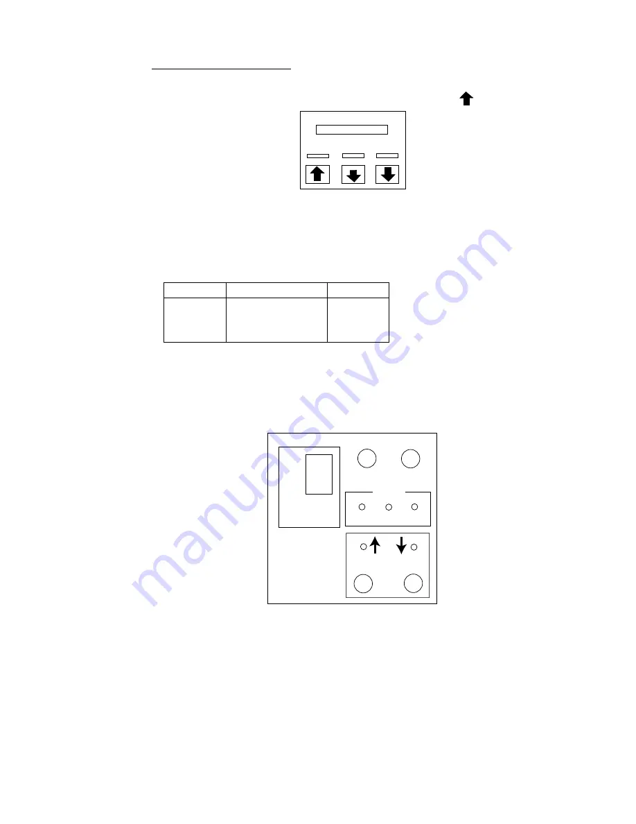
2. Confirm that the 5V and UP lamps on the raise/lower control box are lit.
3. Remove the cover of the raise/lower control box and use a multimeter to
measure the following voltages:
Terminal Terminal
No.
Voltage
TB-C101
(1) – (2), (6) –(7)
(2) – (3), (7) – (8)
(1) – (3), (6) –(8)
220 VAC
220 VAC
220 VAC
4. In the raise/lower control box, set the TEST/NORMAL switch to TEST. Press
the [DOWN] switch to confirm that the transducer lowers. Also, while the
transducer is being lowered, check that the MD LED lights when the MD L.
SW kicks. Note that the MD L. SW does not stop the transducer when the
TEST/NORMAL switch is in the TEST position.
OFF
TEST
NORMAL
5V
L.SW
UP MD DN
UP DOWN
Control unit (for the hull unit)
5. Press and release [DOWN] switch. Confirm that the transducer stops at the
moment the switch is released.
6. Press the [DOWN] switch again. Confirm that the transducer stops at the
moment the lower limit switch kick.
7. Confirm that the [UP] switch operators in a similar manner.
Summary of Contents for FSV-24
Page 8: ...This page is intentionally left blank ...
Page 62: ...This page is intentionally left blank ...
Page 71: ......
Page 72: ......
Page 73: ......
Page 74: ......
Page 75: ......
Page 76: ......
Page 77: ......
Page 78: ......
Page 79: ......
Page 80: ......
Page 81: ......
Page 82: ......
Page 83: ......
Page 84: ......
Page 85: ......
Page 86: ......
Page 87: ......
Page 88: ......
Page 89: ......
Page 90: ......
Page 91: ......
Page 92: ......
Page 93: ......
Page 94: ......
Page 95: ......
Page 96: ......
Page 97: ......
Page 98: ......
Page 99: ......
Page 100: ......
Page 101: ......
Page 102: ......
Page 103: ......
Page 104: ......
Page 105: ......
Page 106: ......
Page 107: ......
Page 108: ......
Page 109: ......
Page 110: ......


