2-16
2.5.4 Connection
1. Open the transceiver unit cover.
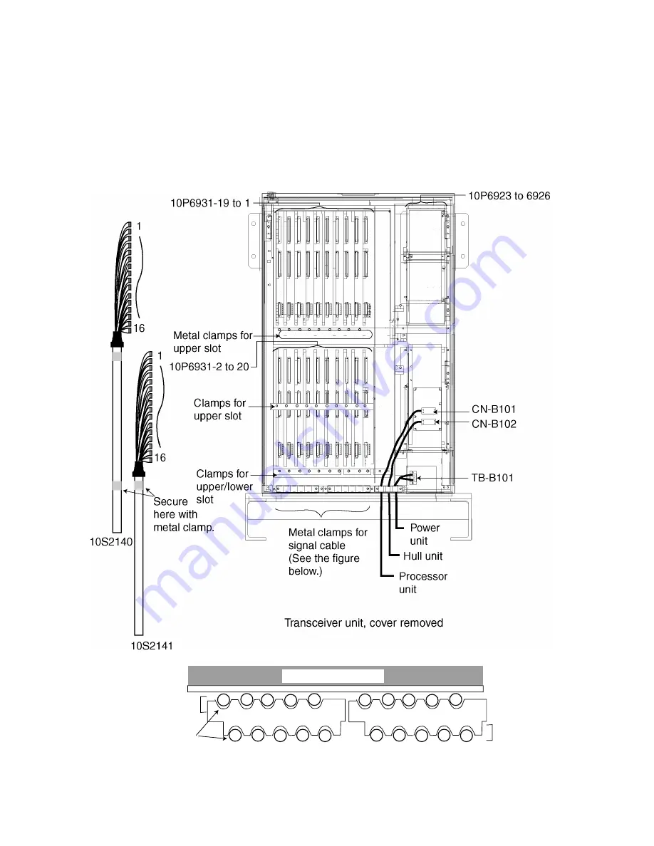
2. Plug the XH connectors at the end of signal cables (10S2140, 10S2141) into
the proper receptacles in the transceiver unit, referring to the labels on the
cables and numbers on the TRX board.
3. Lead the cables into the transceiver unit appropriately. For clamping, lay the
cables as shown in the figure “Cable location at metal clamp, top view” below.
4. Unfasten the cable fixing strip after wiring the hull unit.
Transceiver unit
Clamps for
lower slot
2
4
6
8
10
11
13
15
17
19
Clumps for
upper slot
12
14
16
18
20
1
3
5
7
9
Cable
number
Cable location at metal clamp, top view
Summary of Contents for FSV-24
Page 8: ...This page is intentionally left blank ...
Page 62: ...This page is intentionally left blank ...
Page 71: ......
Page 72: ......
Page 73: ......
Page 74: ......
Page 75: ......
Page 76: ......
Page 77: ......
Page 78: ......
Page 79: ......
Page 80: ......
Page 81: ......
Page 82: ......
Page 83: ......
Page 84: ......
Page 85: ......
Page 86: ......
Page 87: ......
Page 88: ......
Page 89: ......
Page 90: ......
Page 91: ......
Page 92: ......
Page 93: ......
Page 94: ......
Page 95: ......
Page 96: ......
Page 97: ......
Page 98: ......
Page 99: ......
Page 100: ......
Page 101: ......
Page 102: ......
Page 103: ......
Page 104: ......
Page 105: ......
Page 106: ......
Page 107: ......
Page 108: ......
Page 109: ......
Page 110: ......


