


1-1
1. MOUNTING
1.1
Antenna Unit
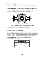
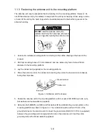
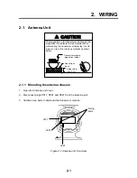
1.1.1 Mounting considerations
•
The antenna unit is generally installed either on top of the wheelhouse or on the radar mast,
on a suitable platform. Locate the antenna unit where there is a good all-round view.
•
No funnel, mast or derrick should be within the vertical beamwidth of the antenna in the bow
direction, especially zero degrees ±5
°
, to prevent blind sectors and false echoes on the radar
picture.
•
It is rarely possible to place the antenna unit where a completely clear view in all directions is
available. Thus, you should determine the angular width and relative bearing of any shadow
sectors for their influence on the radar at the first opportunity after fitting.
•
Locate the antenna of a direction finder clear of the antenna unit to prevent interference to the
direction finder. A separation of more than two meters is recommended.
•
To lessen the chance of picking up electrical interference, avoid where possible routing the
signal cable near other onboard electrical equipment. Also avoid running the cable in parallel
with power cables.
•
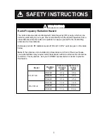
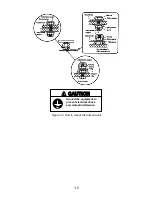
A magnetic compass will be affected if placed too close to the antenna unit. Observe the
following compass safe distances to prevent deviation of a magnetic compass: Standard
compass, 1.70 m (FR-2115-B), 2.10 m (FR-2125-B), Steering compass, 0.90 m (FR-2115-B),
1.20 m (FR-2125-B).
•
Do not paint the radiator aperture, to ensure proper emission of the radar waves.
•
The signal cable run between the antenna and the display is available in lengths of 15 m
(standard), 20 m, and 30 m. Whatever length is used it must be unbroken; namely, no splicing
allowed.
•
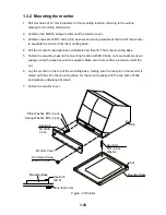
The antenna base is made of cast aluminum. To prevent electrolytic corrosion of the antenna
base, use the seal washers and corrosion-proof rubber mat.
•
Deposits and fumes from a funnel or other exhaust vent can adversely affect the aerial
performance and hot gases may distort the radiator portion. The antenna unit must not be
mounted where the temperature is more than 70
°
C.
•
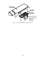
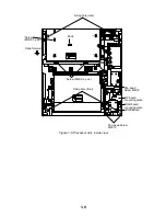
Leave sufficient space around the unit for maintenance and servicing. See the antenna unit
outline drawing for recommended maintenance space.
Summary of Contents for FR-2115-B
Page 56: ......
Page 57: ......
Page 58: ......
Page 59: ......
Page 60: ......
Page 61: ......
Page 62: ......
Page 63: ......
Page 64: ......
Page 65: ......
Page 66: ......
Page 67: ......
Page 68: ......
Page 69: ......
Page 70: ......
Page 71: ......
Page 72: ......
Page 73: ......
Page 74: ......
Page 75: ......
Page 76: ......
Page 77: ......
Page 78: ......
Page 79: ......
Page 80: ......
Page 81: ......
Page 82: ......
Page 83: ......
Page 84: ......
Page 85: ......
Page 86: ......
Page 87: ......
Page 88: ......
Page 89: ......