


4-13
4.4 Performance Monitor PM-30
Necessary parts: PM-30 and OP03-150 (Code no. 008-485-490)
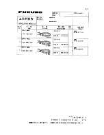
Name Type
Code
No.
Qty
PM-IN Board
03P9225
008-487-620
1
Pan-head Screw B
M3X8 C2700W
000-881-404
3
Connector Assy.
VH3P-L300-AA
000-141-014
2
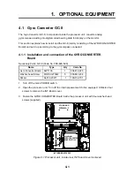
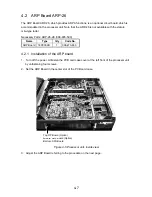
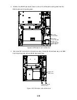
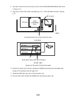
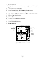
1. Open the processor unit. Unfasten three screws to remove the RGB Board together with its
mounting plate. Unfasten the monitor cable at the RGB Board. (See Figure 4-9 on page 4-10
for location.)
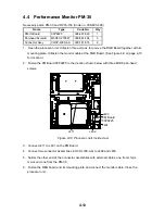
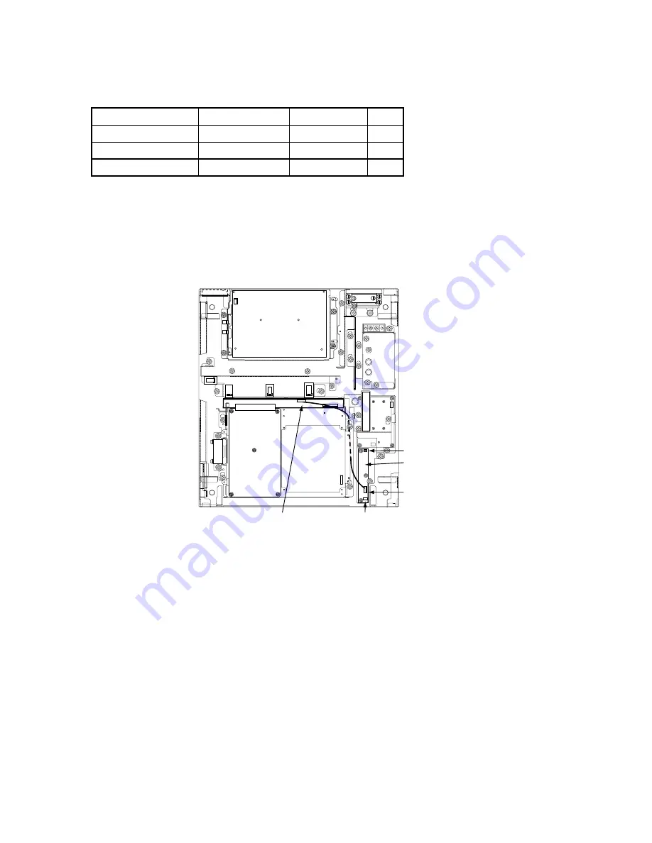
2. Fasten the PM Board 03P9225 to the location shown below with three M3X8 pan-head
screws.
J401
J411
PM Board
03P9225
J402
J403
Figure 4-13 Processor unit, inside view
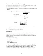
3. Connect J411 to J401 on the PM Board.
4. Connect two connector assemblies (VH3P-L300-AA) to J402 and J403.
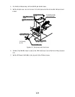
5. Solder the other end of the connector assemblies with external cables, one from ship's
mains and one from the PM-30.
6. Fasten the RBG board and its mounting plate and connect the monitor cable. Close the
processor unit.
Summary of Contents for FR-2115-B
Page 56: ......
Page 57: ......
Page 58: ......
Page 59: ......
Page 60: ......
Page 61: ......
Page 62: ......
Page 63: ......
Page 64: ......
Page 65: ......
Page 66: ......
Page 67: ......
Page 68: ......
Page 69: ......
Page 70: ......
Page 71: ......
Page 72: ......
Page 73: ......
Page 74: ......
Page 75: ......
Page 76: ......
Page 77: ......
Page 78: ......
Page 79: ......
Page 80: ......
Page 81: ......
Page 82: ......
Page 83: ......
Page 84: ......
Page 85: ......
Page 86: ......
Page 87: ......
Page 88: ......
Page 89: ......