


4-16
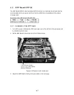
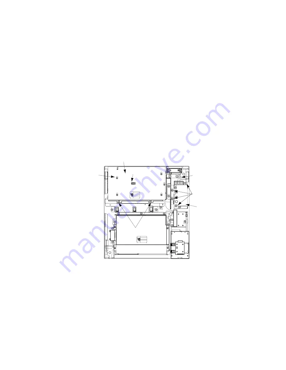
1. Open the processor unit.
2. Follow a) and b) of "how to access rear-left fixing hole" on page 7 to remove the PTU Board
cover.
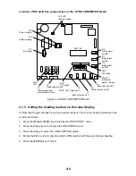
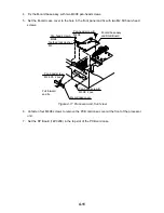
3. Unplug all connectors from the PTU Board.
4. Loosen the screws fixing the PTU Board, and then remove the PTU Board.
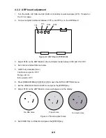
5. Fasten new PTU Board with screws removed in step 4.
6. Plug in six connectors to their proper locations on the PTU Board. Do not connect J101.
7. Loosen four screws fixing the AC filter.
8. Fasten new filter.
9. Connect cable from filter to J101 on the PTU Board.
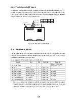
10. Fasten the PTU board cover.
11. Connect power cable from ship's mains.
12. Close the processor unit.
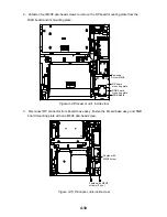
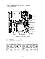
J106
J105
J104
J103
J446
J466
J462
J465
Screw
(M3X8, 5 pcs.)
*
*
*
*
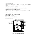
Slide forward
↓
Screw (M4X8, 2 pcs.)
Knob
Filter
(Shown:
AC type)
PTU Board (behind shield cover)
Power cable
leads
*
Unfasten
screws.
Figure 4-15 Processor unit, inside view
Summary of Contents for FR-2115-B
Page 56: ......
Page 57: ......
Page 58: ......
Page 59: ......
Page 60: ......
Page 61: ......
Page 62: ......
Page 63: ......
Page 64: ......
Page 65: ......
Page 66: ......
Page 67: ......
Page 68: ......
Page 69: ......
Page 70: ......
Page 71: ......
Page 72: ......
Page 73: ......
Page 74: ......
Page 75: ......
Page 76: ......
Page 77: ......
Page 78: ......
Page 79: ......
Page 80: ......
Page 81: ......
Page 82: ......
Page 83: ......
Page 84: ......
Page 85: ......
Page 86: ......
Page 87: ......
Page 88: ......
Page 89: ......