background image

1.  OPERATION

13

1.10

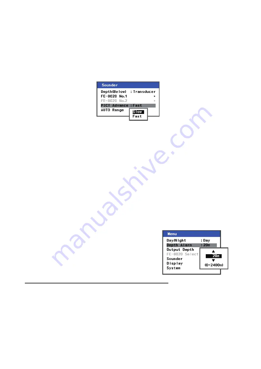
PICT Advance

The picture advance menu allows you determine the speed at which the vertical scan lines run 
across the screen. 

1. Press the 

MENU/ESC

 key to open the Main menu.

2. Select [Sounder] using 

 or 

, then press the 

ENT

 key.

3. Select [PICT Advance] using 

 or 

, then press the 

ENT

 key. This will open a pop-up 

window.

4. Select [FAST] or [SLOW] as appropriate, using 

 or 

, then press the 

ENT

 key.

[FAST] picture advance expands the echo sideways across the screen. This is useful when 
studying a rough bottom closely.
[SLOW] picture advance compresses the echo allowing for close inspection when the bottom 
is smooth. 

5. Press the 

MENU/ESC

 key twice to close the menu.

1.11

How to Set the Depth Alarm

The depth alarm sounds when the seabed is shallower than the depth setting. The default setting 
is 20 meters.

Note: 

The depth setting distance is measured from the face of the transducer.

The depth can be adjusted by following the procedure below:

1. Press the 

MENU/ESC

 key to open the Main menu.

2. Select [Depth Alarm] using 

 or 

, then press the 

ENT


key. This will open a pop-up window.

3. Choose the depth at which you wish the alarm to activate, 

using 

 or 

, then press the 

ENT

 key to apply the settings 

and close the pop-up window.
The available range is 0 to 2400m.

4. Press the 

MENU/ESC

 key once to close the menu.

How to acknowledge the alarm and silence the alarm buzzer

You can acknowledge the alarm, and silence the buzzer, by pressing the 

ALARM/ACK

 (Alarm 

Acknowledge) key.

Summary of Contents for FE-800

Page 1: ...NAVIGATIONAL ECHO SOUNDER FE 800 OPERATOR S MANUAL www furuno com Model...

Page 2: ......

Page 3: ...nner Road Havant Hampshire PO9 1QY U K All brand product names trademarks registered trademarks and service marks belong to their respective holders How to discard this product Discard this product ac...

Page 4: ...er at the switchboard and contact a FURUNO service technician Mandatory Action Prohibitive Action WARNING CAUTION Warning Caution Indicates a potentially hazardous situation which if not avoided could...

Page 5: ...1011 3 Code No 100 236 233 Warning Label s Warning label s is are attached to the equipment Do not remove the label s If a label is missing or damaged contact a FURUNO agent or dealer about replaceme...

Page 6: ...isplayed depth 19 1 21 3 How to adjust the dimmer presets 20 2 SYSTEM MENU 21 2 1 How to Set the Basic Range Scale 21 2 2 How to Set Transducer Parameters 22 2 2 1 Bottom level 22 2 2 2 TVG level 23 2...

Page 7: ...Features The FE 800 is a colour navigation echo sounder which operates with 50 or 200 kHz frequency The FE 800 is comprised of a control unit transceiver matching box and transducer Echoes are output...

Page 8: ...tions please refer to our website www furuno com for further information about RoHS conformity declarations Disclosure of Information about China RoHS With regards to China RoHS information for our pr...

Page 9: ...UNIT FE 8020 KP Output IEC 61162 1 x 2 IEC 61162 1 x 4 POWER FAIL IEC 61162 450 LAN JUNCTION BOX JISF8821 1MO MATCHING BOX MB 504 TRANSDUCER 200B 8B TRANSDUCER 50B 6B MATCHING BOX MB 502 Equipment cat...

Page 10: ...display from any location in the menus MENU ESC Displays closes the menu Returns one level in the menu tree unless on first level and ENT Adjusts key brilliance Menu screens Moves up down levels in t...

Page 11: ...the self test completes the mode used before the FE 800 was turned off is activated You can now change modes freely See section 1 4 Note If any errors occur during the self test process the self test...

Page 12: ...location in the Day Dusk 1 Night 1 Dusk setting is available when Dimmer Mode 2 is ECDIS 2 According to the Dimmer Mode setting it is selectable that panel brilliance change from the external equipme...

Page 13: ...ress the ENT key 4 Press the MENU ESC key once to close the menu The default setting for Day Dusk and Night modes are shown in the table as below In case of the brightness related change from the exte...

Page 14: ...ainte nance icon Indicates that the remote access function from external equipment is ac tivated This icon is shown when Management Profile is set to ON at installation 4 Range setting Shows the curre...

Page 15: ...ms or a brief description of the selected menu item Note Alarm messages take priority over menu descriptions 11 Transducer Shows the location of the transducer and output signal 12 Sounding echo Shows...

Page 16: ...s echo readings can be accessed by using or to move the cursor Interval setting Amount of data stored 2 min 24 hours 1 min 12 hours 5 sec 1 hour Number Description 1 FORE AFT depth history 2 Time loca...

Page 17: ...splay shows the current echo readings EPFS devices are often referred to as talkers Below is a list of talker types and their respective display names which can be used with the FE 800 Number Descript...

Page 18: ...1 If FE 8020 No 2 is not enabled in the Service Menu the following menu items are grey and not selectable Main menu FE 8020 Select Sounder menu FE 8020 No 2 System menu Parameters FE 8020 No 2 System...

Page 19: ...ion are of a dual transducer configuration Single transducer configuration pop up menus will change slightly 1 7 1 How to adjust the gain 1 Press the MENU ESC key to open the Main menu 2 Select Sounde...

Page 20: ...the auto gain 1 Press the MENU ESC key to open the Main menu 2 Select Sounder using or then press the ENT key 3 Select the transceiver FE 8020 No 1 or FE 8020 No 2 as appropriate using or then press...

Page 21: ...r then press the ENT key to apply the settings and close the pop up window The available settings are 0 to 7 9 Press the MENU ESC key three times to close the menu 1 9 Interference Interference from o...

Page 22: ...NU ESC key twice to close the menu 1 11 How to Set the Depth Alarm The depth alarm sounds when the seabed is shallower than the depth setting The default setting is 20 meters Note The depth setting di...

Page 23: ...appears 4 Press the DISP key to return to the main display 1 13 How to Output to External Equipment The FE 800 can output depth information from one transceiver to external equipment such as ECDIS To...

Page 24: ...When the message disappears the switch between transceivers is complete 4 Press the MENU ESC key once to close the menu 1 15 How to Set the Depth Below Surface DBS The depth reading can be referenced...

Page 25: ...020 No 1 or FE 8020 No 2 then press the ENT key 4 Select Draught then press the ENT key This will open a pop up window 5 If using a single transducer configuration skip to step 8 For dual transducer c...

Page 26: ...Press the DISP key to close the logbook How to change the logging interval The logging interval for each entry can be adjusted in the menu by doing the following 1 Press the MENU ESC key to open the M...

Page 27: ...MENU ESC key to open the Main menu 2 Select Display using or then press the ENT key 3 Select Course using or then press the ENT key This will open a pop up window 4 Select the course display using or...

Page 28: ...ransducers connected you may change the manner in which the echoes are displayed on screen 1 Press the MENU ESC key to open the Main menu 2 Select Display using or then press the ENT key 3 Select Echo...

Page 29: ...iate When DUAL is selected the sec ondary depth reading is displayed in a box at the bottom of the display 5 Press the DISP key to close the menus 1 21 3 How to adjust the dimmer presets You can chang...

Page 30: ...Select Range using or then press the ENT key This will open a pop up window 4 Select the basic range scale using or then press the ENT key This will open a pop up window 5 Adjust the range if required...

Page 31: ...four times to close the menu 2 2 1 Bottom level If the depth indication is unstable or the seabed cannot be displayed steadily notwithstanding the adjustment of the control panel you may adjust the bo...

Page 32: ...off the FE 800 switch transducers at the Junction Box and then turn on the FE 800 again 2 2 3 Echo offset The echo offset feature functions to compensate for too weak or too strong echo level If the...

Page 33: ...t System using or then press the ENT key 3 Select Parameters using or then press the ENT key 4 Select Bottom Link RNG using or then press the ENT key This will open a pop up window 5 Select OFF or ON...

Page 34: ...on Follow the procedure below to access the Active Alert list Note that the Alert log can also be shown through menu operation 1 Press the MENU ESC key to open the Main menu 2 Select System using or t...

Page 35: ...T key 4 Select Alert Log using or then press the ENT key Note The above example shows alerts which are output under Alert I F2 settings The alert ID differs depending on the alert format selected at i...

Page 36: ...th only the final three digits depending on the Alarm Mode selected To adjust the alert settings do the following 1 Press the MENU ESC key to open the Main menu 2 Select System using or then press the...

Page 37: ...dge each individual alert Note All notifications are stored in the Alert LOG Depending on your Alert mode Alert ID can be in two formats 3 digit or 4 digit followed by in stance number for example 1 S...

Page 38: ...fixed time period Alert category An alert is further classified by category A B or C according to its degree of severity or source Note 1 This equipment does not provide the functional alert group fun...

Page 39: ...ee second ON time Buzzer Silent Alarm Red Active acknowledged icon is displayed steadily Alarm Red Active responsibility transferred icon is displayed steadily Alarm Red Active unacknowledged notifica...

Page 40: ...at of Warning alert For a Warning alert to become an Alarm alert the alert priority must be changed In most cases the Warning alert is simply repeated In general only the alerts specified by the IMO c...

Page 41: ...reverts to the internal clock and the time is displayed with an as terisk 2 9 1 External time 1 Press the MENU ESC key to open the Main menu 2 Select System using or then press the ENT key 3 Select Sh...

Page 42: ...n press the ENT key 6 Adjust the parameter using or then press the ENT key to apply the settings and close the pop up window To keep the default setting press the DISP key or the MENU ESC key 7 Press...

Page 43: ...o select a digit to set To complete the setting process for the IP address press until the cursor passes the final digit 6 Select DEST Port using or then press the ENT key A pop up window to set the d...

Page 44: ...he figure below is an example of the information screen 1 Press the MENU ESC key to open the Main menu 2 Select System using or then press the ENT key 3 Select Information using or then press the ENT...

Page 45: ...degreaser or an antifog solution as they can strip the coating from the LCD 3 3 Transducer Maintenance Marine life on the transducer face will result in a gradual decrease in sensitivity Check the tra...

Page 46: ...se for AC input 2 pcs FGMB 250V 2A PBF 000 157 497 10 SYMPTOM PROBABLE CAUSE REMEDY No picture no reading measure Low voltage Check the supply voltage Fuse blown Refer to section 3 5 Power cable damag...

Page 47: ...er DEPTH BELOW Transducer Keel Surface FE 8020 No 1 Draught 0 0m to 30 0m Manual GAIN 0 to 9 Default 5 AUTO GAIN OFF ON AUTO GAIN ADJ 10 to 10 Default 0 Clutter 0 to 7 Default 7 IR OFF IR1 IR2 IR3 FE...

Page 48: ...c Range6 200 Default 200m Basic Range7 201 to BR8 1 Default 400m Basic Range8 BR7 1 to 2400 Default 800m System Parameters No 1 Parameters TVG 0 to 9 Default 5 TVG Distance 1m to 100m Echo Offset 20 t...

Page 49: ...F ON Data Recorder DEST IP Address 000 000 000 000 to 255 255 255 255 Default 172 031 018 001 DEST Port 00000 to 65535 Default 11000 EXT Setting OFF ON Remote Dimmer OFF ON Information FE 8010 FE 8020...

Page 50: ...L board 12P1003 PWR board 12P1002 MAIN board 12P1000 TRX board 12P1001 FIL board Remove MAIN board to show TRX board Remove MAIN board to show TRX board DISP board 12P1004 Remove bracket to show MCN b...

Page 51: ...emonstration MENU Menu DEST Destination MPH Miles Per Hour DISP Display NAV Navigation DRAUGHT Draught NMEA National Marine Electronics Association ENT Enter Nov November EPFS Electronic Position Fixi...

Page 52: ...BREVIATIONS AP 6 II Integrated Instrumentation TRANSDUCER XDR Transducer IN Integrated Navigation TVG Time Varied Gain IR Interference Rejector TX Transmit I F Interface UTC Universal Time Coordinated...

Page 53: ...A 3031 4 Depth at aft2 transducer is shallower than that set for the alarm LOST MEAS TCVR1 TX volt age ERR stopped MEAS Warning B 3008 1 Transceiver 1 PWR board or TRX board may be dam aged Voltage i...

Page 54: ...be tween display unit and transceiver 1 Consult a FU RUNO techni cian LOST TCVR TCVR2 COM ERR stops MEAS Caution B 3003 2 Communication error be tween display unit and transceiver 2 FAN SPEED LOW TCV...

Page 55: ...RX board may be damaged Voltage is not within safe guidelines TCVR2 RX voltage ERR stopped MEAS Warning B 112 Transceiver 2 PWR board or TRX board may be damaged Voltage is not within safe guidelines...

Page 56: ...2 minute intervals 12 hours at 1 minute intervals 1 hour at 5 second intervals 1 9 Display mode NAV Basic echo presentation with the depth below transducer keel or sea surface HISTORY Historical prese...

Page 57: ...efault NAVD 3 5 Other network functions except IEC61162 450 SSDP HTTP Syslog Furuno management Protocol FMP Optional data recording software communication protocol 3 6 Alarm output Contact closure Nor...

Page 58: ...33 Key sound 33 L Logbook 17 logging interval 17 M Maintenance and troubleshooting 36 alarm list 28 battery replacement 37 cleaning the display 36 fuse replacement 37 transducer maintenance 36 Menu op...

Page 59: ......

Page 60: ...al is elemental chlorine free FURUNO Authorized Distributor Dealer 9 52 Ashihara cho Nishinomiya 662 8580 JAPAN A MAY 2014 Printed in Japan All rights reserved H JUL 01 2022 Pub No OME 23840 H YOTA FE...

Reviews: