


eRide
OPUS 6/
eRide
OPUS 7 GV-8620/ GV-8720
Dead Reckoning User
’
s Guide
SE16-900-002-02
5
FURUNO ELECTRIC CO., LTD. All rights reserved.
5 IMU Sensor Installation
For the installation of the IMU sensor, the DR receiver has specification values for the inclination and the
deviation of the coordinate system of the vehicle and the IMU sensor. The DR receiver has a function to
correct the inclination and the deviation within the specification value.
(1) Method of automatically correcting the inclination and the deviation of installation angle by the Auto
Orientation function
(2) Method of presetting the inclination of the known installation angle by the misalignment command
With these functions, it is possible to correct and eliminate the output error of the IMU sensor caused by the
inclination and deviation.
The Auto Orientation function can also expand the range of angles that can be automatically corrected by
AUTOORIENT command.
<Definition of coordinate system and axis>
Here are definitions of axis against sensor unit installation angle:
-
Direction of forward movement: X-axis
-
Horizontal to the direction of movement: Y-axis
-
Vertical to the direction of movement: Z-axis
Rotation angles to the each axis are defined as follows:
-
Rotation angle around the X axis:
Δθ
X
Roll angle
-
Rotation angle around the Y axis:
Δθ
Y
Pitch angle
-
Rotation angle around the Z axis:
Δθ
Z
Yaw angle
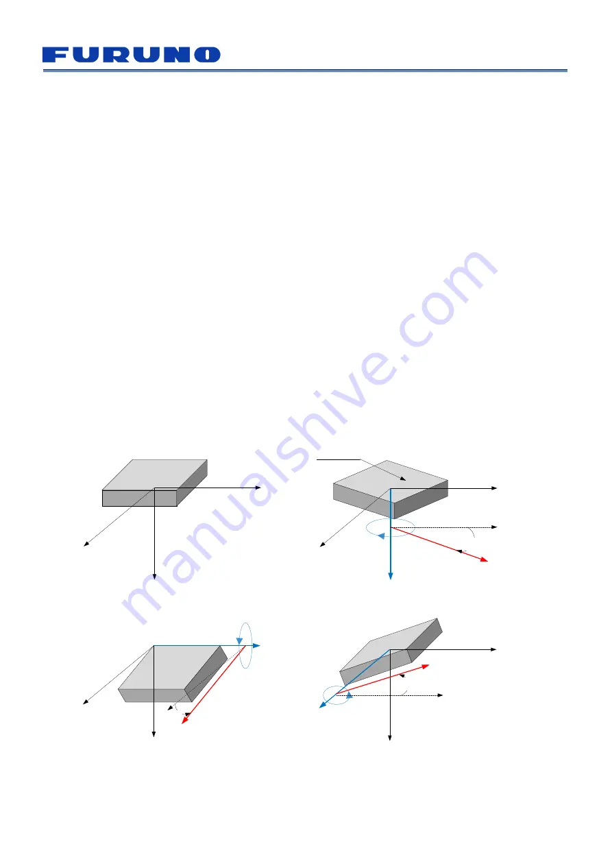
Figure 5.1 (a) to (d) shows inclination against each axis.
Z
X
Y
(a) No inclination
Z
X
Y
(b) Inclines
Δθ
Z
to the direction of movement
Z
X
Y
(c) Inclines
Δθ
X
to the horizontal direction
Z
X
Y
(d) Inclines
Δθ
Y
to the height direction
Δθ
Y
0
0
0
Surface
0
Direction of
movement
Δθ
Z
Δθ
X
Figure 5.1 Sensor Unit Installation Angle Definition


