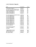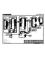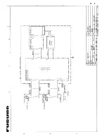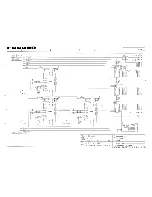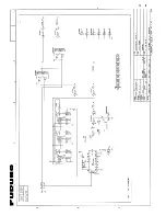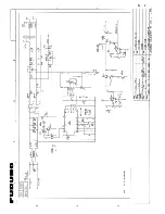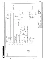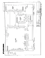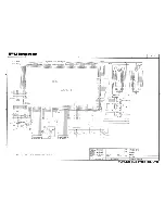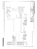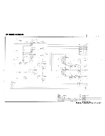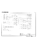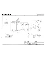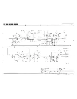
List of Schematic Diagrams
Title
Drawing No.
Page
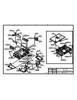
Interconnection Diagram
C1322-C01 S-1
Interconnection Diagram (With I/F unit) C1322-C02
S-2
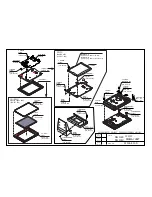
MU-100C Display Unit General Diagram C1316-K01
S-3
DISP Board (06P0238) 1/4
C1316-K08
S-4
DISP Board (06P0238) 2/4
C1316-K09
S-5
DISP Board (06P0238) 3/4
C1316-K10
S-6
DISP Board (06P0238) 4/4
C1316-K11
S-7
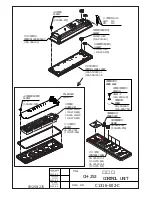
CH-273 Transceiver Unit General Drawing C1322-K01
S-8
CPU Board (06P0258) 1/5
C1322-K02
S-9
CPU Board (06P0258) 2/5
C1322-K03
S-10
CPU Board (06P0258) 3/5
C1322-K04
S-11
CPU Board (06P0258) 4/5
C1322-K05
S-12
CPU Board (06P0258) 5/5
C1322-K06
S-13
TRX Board (06P0241) 1/4
C1316-K12
S-14
TRX Board (06P0241) 2/4
C1316-K13
S-15
TRX Board (06P0241) 3/4
C1316-K14
S-16
TRX Board (06P0241) 4/4
C1316-K15
S-17
PWR Board (06P0242) 1/2
C1316-K03
S-18
PWR Board (06P0242) 2/2
C1316-K04
S-19
RPA
Board
(06P0259)
C1322-K07
S-20
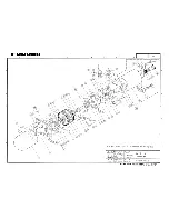
Hull Unit General Drawing
C1271-023
S-21
Train/Tilt Driver Board
C1271-001
S-22
Soundome
C1271-036
S-23
IF-8000 Interface Unit 1/2
C1316-K06
S-24
IF-8000 Interface Unit 1/2
C1316-K07
S-25
REM Board (06P0247)
C1316-K25
S-26
BS-704 Inclinometer
C1259-041
S-27
CH-270 Service Manual
Summary of Contents for CH-270
Page 1: ...COLOR SEARCHLIGHT SONAR CH 270...
Page 13: ...10 58 59 6 6 DRV 06P0154 Hull Unit XDR Slip ring Figure 2 1 Signal Flow in Transmitter...
Page 14: ...11 Hull unit XDR Slip ring 6 6 59 58 Figure 2 2 Signal Flow in Receiver...
Page 19: ...16 Figure 2 5 TRANSCEIVER UNIT CPU J2 3 4 3 4 5 6 J10 5 6 7 8 CR16 U17 U34 191 R104 R105...
Page 23: ...20 DRV Board 06P0154...
Page 54: ......
Page 55: ......
Page 64: ......
Page 65: ......
Page 66: ......
Page 67: ......
Page 68: ......
Page 69: ......
Page 70: ......
Page 71: ......
Page 72: ......
Page 73: ......
Page 74: ......
Page 75: ......
Page 76: ......
Page 77: ......
Page 78: ......
Page 79: ......
Page 80: ......
Page 81: ......
Page 82: ......
Page 83: ......
Page 84: ......
Page 85: ......
Page 86: ......
Page 87: ......
Page 88: ......

