background image

10


58

59

6

6

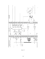
DR

V 06P0154

Hull Unit

XDR

(Slip ring)


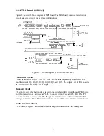
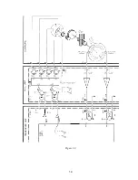
Figure 2.1    Signal Flow in Transmitter


Summary of Contents for CH-270

Page 1: ...COLOR SEARCHLIGHT SONAR CH 270...

Page 2: ...0798 65 4200 0798 65 4200 FIRST EDITION FIRST EDITION JUL JUL 2004 2004 Printed in Japan Printed in Japan All rights reserved All rights reserved Pub No Pub No SME 13220 A SME 13220 A 00015124100 0001...

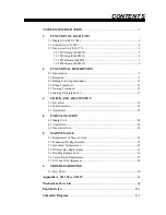
Page 3: ...Transducer 15 2 6 Braking Tilt Train Motor 17 3 CHECK AND ADJUSTMENT 3 1 Test Points 18 3 2 LED Indication 21 3 3 Adjustment 22 4 PARTS LOCATION 4 1 Display Unit 24 4 2 Control Unit 26 4 3 Transceiver...

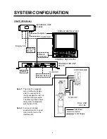
Page 4: ...Option Local Supply CONTROL BOX CONTROL UNIT CH 252 SECTOR TRAIN RANGE TILT MAIN SUB FULL HALF FAST SCAN BRILL TARGET MENU R B EVENT CUSTOM MODE DISPLAY MODE POWER XDR GAIN HULL UNIT CH 184 Note 1 Th...

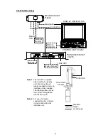
Page 5: ...LL UNIT CH 181 12 24 VDC Note 1 The CH 270 is supplied with or without a display unit For connection of locally supplied monitor an interface unit is provided The drawing above shows the system config...

Page 6: ...tching regulator circuit The LCD interface circuit converts the analoge R G B signals from the transceiver unit into six bit digital R G B signals with a A D converter H SYNC V SYNC and CLK dot clock...

Page 7: ...Diagram of Control Unit The control unit consists of the control panel and PNL board The CPU on PNL board reads the settings on the control panel and sends the data to the CPU in transceiver unit thro...

Page 8: ...SYNC and clock signals for the display unit 5 To read settings on the control panel 6 To receive and send I O signals through NMEA port 7 To receive data from the motion sensor 8 To generate character...

Page 9: ...Q10 Q12 Q13 and Q15 The output level of TRX board is determined with B voltage VTX signal Receiver Circuit The signal received by the transducer is sent to the wide band filter circuit through PRA bo...

Page 10: ...als to send them to PWR board via the display unit The PWR board generates 5V 5V 12V 12VD and B voltage VTX The 12VD voltage 12VA is supplied to the display unit via CPU board The VTX voltage is deter...

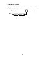
Page 11: ...rd 06P0259 locates in the transceiver unit Figure 1 6 shows the block diagram of PRA board From Transmitter Matching Transformer Trap Circuit To Transducer Resonance Circuit Pre Amplifier Receiving Si...

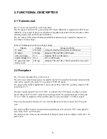
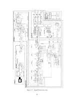
Page 12: ...P6 and TP8 on TRX board with Dummy Load 2 2 Reception Fig 2 2 shows the signal flow in the receiver The echo received by the transducer is amplified by the Pre Amplifier board and mixed with the local...

Page 13: ...10 58 59 6 6 DRV 06P0154 Hull Unit XDR Slip ring Figure 2 1 Signal Flow in Transmitter...

Page 14: ...11 Hull unit XDR Slip ring 6 6 59 58 Figure 2 2 Signal Flow in Receiver...

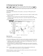
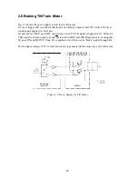
Page 15: ...r as a brake Hull unit DRV board CPU board LOWER J10 3 1 J2 1 2 R L Cont Signal RAISE Figure 2 3 Raise Lower Circuit Raise Operation The transducer raises in the following sequence 1 When R L CONT sig...

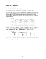
Page 16: ...posite direction Table 2 2 Clock Cycle DN UP H Clock Cycle DN UP L Output 1 2 3 4 5 6 7 8 1 2 3 4 5 6 7 8 1 L L L L L H H H H H L L L L L H 2 L L L H H H L L L H H H L L L L 3 L H H H L L L L L L L H...

Page 17: ...14 Figure 2 4 TRANSCEVER UNIT CPU U17 CPU J2 TI CLK TIM1 TI UP DN TIM2 5 6 92 197 CR41 CR18 TI 93 TI8 U39 U33 J10 11 12 9 10...

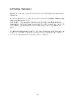
Page 18: ...rates a Heading signal TR FORE when the transducer faces toward the bow The TR FORE signal is sent to the CPU as TR 0 At every power on the CPU searches TR 0 signal If the CPU does not detect TR 0 sig...

Page 19: ...16 Figure 2 5 TRANSCEIVER UNIT CPU J2 3 4 3 4 5 6 J10 5 6 7 8 CR16 U17 U34 191 R104 R105...

Page 20: ...nd ON respectively when TI CLK signal is applied to U2 When TI CLK signal is absent outputs Q and Q are held to LOW and HIGH respectively causing that Q1 goes ON and Q2 OFF Thus 6V is applied to the t...

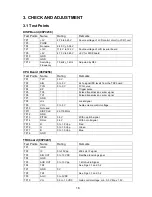
Page 21: ...KP Trigger pulse TP5 TX0 Pulsed transmission carrier signal TP6 TX1 Pulsed transmission carrier signal TP7 GND TP8 LCL Local signal TP9 VOL 0 to 5 V Audio volume control voltage TP10 Not used TP11 DIS...

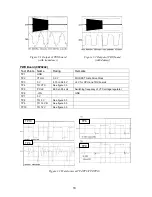
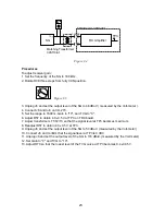
Page 22: ...D TP2 VTX G 0 9 V MOS FET Gate Drive Clock TP3 5 V 4 75 to 5 25 V 5 V for CPU and TRX boards TP4 TO VTX See figure 3 3 TP5 P CLK 68 0 0 05 kHz Switching frequency of VTX voltage regulator TP6 VIN GND...

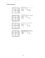
Page 23: ...20 DRV Board 06P0154...

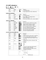
Page 24: ...ng CR15 RAISE ON when upper limit switch is activated CR16 TR FORE ON when Heading is generated CR17 LOWER ON when lower limit switch is activated CR18 TI93 ON when TI93 signal is generated CR41 TI8 O...

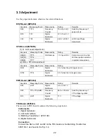
Page 25: ...screen 2 ROLL PITCH Adjustment Adjusters Measuring Points Measured by Rating R101 TP13 Digital Multimeter 3 5 V when the pitch angle is zero R102 TP14 Digital Multimeter 3 5 V when the roll angle is...

Page 26: ...ange to 1600 m Gain to 10 and TVG to 0 6 Adjust R57 to obtain 4 0 0 5 V at TP3 on TRX board 7 Adjust transformers T1 T2 T3 so that the signal level at TP3 becomes maximum 8 Readjust R57 to obtain 4 0...

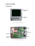
Page 27: ...IDEO IN CONT 4 PARTS LOCATION 4 1 Display Unit Figure 4 1 Display Unit Front View Figure 4 2 Display Unit LCD PCB Assembly LCD Display Unit MU100C Control Unit CH 252 DISP Board 06P0238 CN3 CN2 CN1 LC...

Page 28: ...25 Figure 4 3 DISP Board 06P0238 TP 7 12V TP 8 5V TP 3 PGND TP10 TP 4 2 4V TP12 TP1 LCD 5V TP11 GND R65 Freq R75 12V Adj F1 3A J1 C63 J4 J6...

Page 29: ...26 4 2 Control Unit Figure 4 4 PNL Board 06P0239 4 3 Transceiver Unit Figure 4 5 Transceiver Unit CH 273 J2 J1 U5 CPU J3 Factory Use Speaker Hull unit Display unit Motion sensor 12 to 32VDC...

Page 30: ...EAKER J4 CR1 VTX J3 J1 J6 CR15 TR TP8 TR1 TP6 TR2 TP3 SIG OUT TP9 AGC TP10 VG TP2 IF R38 GAIN R57 Max Gain R70 Min Gain GND J7 WIDE NARROW TP4 GND TP5 Audio R103 AUD VOL Q15 Q13 Q12 Q10 Q9 Q7 Q6 Q4 TR...

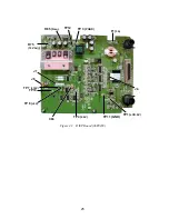
Page 31: ...TX1 TP4 KP TP8 LCL C38 CR6 CR11 CR12 CR15 CR17 CR16 CR18 CR41 TP18 GND R101 R102 TP9 VOL TP11 DISP CLK TP14 ROLL R86 R87 R88 from left TP12 GND TP13 PITCH TP17 TP16 TP15 Figure 4 8 CPU Board 06P0258 T...

Page 32: ...0242 Figure 4 10 PRA Board 06P0259 TP8 To 5V TP12 VIN TP9 To 12VD TP10 To 12V TB1 F1 10A CR12 5V TP4 To VTX TP6 VIN R34 5V ADJ R29 FREQ ADJ R13 VTX ADJ CR1 VTX TP1 GND TP2 VTX G TP3 5V TP5 P CLK CR9 I...

Page 33: ...30 Figure 4 11 Raise Lower Unit 06P0147 F1 4A F2 12V 4V 24V 3A S1 S3 R3 S2 R4 TRAIN Board 06P0154...

Page 34: ...31 Figure 4 12 TRAIN Board 06P0154 Figure 4 13 Raise Lower Unit CR1 Q2 Q3 Q1 J3 CR2 CR3 CR6 to CR9 from left J6 J5 J2 Q4 Q5 Q6 Q7 Q8 Q9 U10 CR16 CR17 J1 B1 TB1 K1...

Page 35: ...7 to 9 mm to the slit on the soundome D and rotate them in the opposite directions each other The upper soundome assembly will slide up by the width of the screwdriver 4 Fix two attachment plates sup...

Page 36: ...assembly into the soundome D marking sure that screw holes are aligned 5 While pressing down the upper dome assembly hand tighten screws 6 Fasten the screws securely in diagonal order especially for t...

Page 37: ...he tilt arm assembly from the transducer by unscrewing eight screws 3 Unsolder transducer lead wires 3 pcs Figure 5 4 Assembling 1 Install the transducer with the transducer support 2 pcs 2 Screw the...

Page 38: ...bolts and disengage the rack gear from the tilt shaft by lifting the gear box Figure 5 6 Assembling 1 Fully lower the tilt shaft 2 Turning the tilt motor gear position the socket see screws for the ti...

Page 39: ...b 06P0158 2 Remove the chassis plate U assembly unscrewing four screws 3 Unscrew two socket set screws to remove the train gear 4 Unscrew four screws to remove the chassis plate D assembly 5 Remove th...

Page 40: ...own below Caution Do not change the bending angle of the carbon brush The angle is set to 30 at the factory Figure 5 10 6 Follow steps 1 to 6 of disassembling procedure in reverse order Note The tilt...

Page 41: ...that improper alignment causes the error message TILT NG and stoppage of whole operation if the mechanical stopper works before 8 or 93 signal is produced or if the two sensors are not activated simul...

Page 42: ...b See Fig 5 16 Be careful not change the tilt angle of the transducer Figure 5 16 6 Fix the tilt code disk by tightening the socket set screws 7 Reinstall the tilt signal 2 pcb 8 Make all interconnect...

Page 43: ...0 8V to 15 6V for 12VDC set and 21 6V to 31 2V for 24VDC set No Yes END No No Check ship s supply No Problem is cleared with new fuse Yes Yes END Check switch S1 No Yes Yes 0V OK Measure the voltage a...

Page 44: ...ship s supply 8ms V 0V Note that train and tilt circuits are driven alternately Check result is OK No Driver circuit has problem Check TI CLK and TI DN UP input signal on DRV board 06P0154 TI CLK U7...

Page 45: ...s on DRV board 06P0154 TR CLK U5 3 sig J1 20 com TR CW CCW U5 4 sig J1 20 com Check result is OK No Driver circuit is faulty Check result is OK Q5 or Q6 Q7 Q8 Q9 is faulty Yes Yes 8ms 45V 0V Check wir...

Page 46: ...5 6V for 12V set and 21 6V to 31 2V for 24VDC set 10 8V to 15 6V for 12V set and 21 6V to 31 2V for 24VDC set No No No No Yes Yes Yes END Yes Check ship s supply Check fuse F1 OK Check motor for short...

Page 47: ...short circuit Measure voltage at collector of Q1 on DRV board 06P0154 10 8V to 15 6V for 12V set and 21 6V to 31 2V for 24VDC set 10 8V to 15 6V for 12V set and 21 6V to 31 2V for 24VDC set Measure v...

Page 48: ...oad 100 ohm 30W between TP6 and TP8 Measure the TX output again Slip ring or Transducer is faulty TX is faulty No Yes No Check the transmitter control signals TXO TXI TXV and VTX DSP board is faulty T...

Page 49: ...ted on CPU board in the transceiver unit Load speaker Metion sensor Remote controller Control unit Display unit Transceiver unit Control Box Soumdome Hull unit CH 254 or CH 255 8 dome Hull unit Transc...

Page 50: ...A board Hull unit UP DOWN Hull unit UP DOWN Transceiver unit RX TX Hull unit Frequency code Matching trans Filter Pre amp XDR T X R X S W Transceiver unit RX TX Hull unit Frequency code Matching trans...

Page 51: ...61 000 061 SOUNDOME SHAFT L 06 007 1572 600 715 720 7 MAIN BODY FLANGE 06 013 2301 1 100 098 691 8 TRUNION PIN 06 013 2302 0 100 098 700 10 GREASE COTTON 9 5SQUARE 0 6M 000 859 103 11 GREASE COTTON RE...

Page 52: ...0 100 099 530 44 BEARING COLLOR 06 013 2225 0 100 099 540 45 SCREW SHAFT 06 013 2218 1 100 099 482 46 MOTOR SPUR GEAR 06 013 2223 0 100 099 520 48 CABLE GLAND PM25 000 801 022 49 CABLE GLAND PM 15 000...

Page 53: ...0 22 TRAIN MOTOR GEAR 06 013 2124 0 100 098 980 23 GEAR BOX COVER 06 013 2128 1 100 099 021 24 SPACER 49 06 013 2111 0 100 098 860 25A SOUNDOME U 06 013 2102 2 100 098 792 SOUNDOME ASSEMBLY CH 1812 24...

Page 54: ......

Page 55: ......

Page 56: ...0 126 024 B SCREW M3 8 000 881 404 LCD NL6448BC33 31 000 142 409 MU100C CH 250 NL6448AC33 29 000 143 337 MU101C FCV 1200L LM MCN BOARD 14P0309 PANEL 06 021 1001 100 279 411 FILTER 86 012 1005 100 262...

Page 57: ...539 CONTROL PANEL 06 021 2011 J 100 279 661 06 021 2001 E 100 279 631 KNOB ASSY NKOB 06 021 2022 100 279 700 D SPRING 6601 P 000 802 139 KNOB 03 144 1603 100 263 751 KNOB ASSY GASKET 03 129 1022 100...

Page 58: ...M4X8 000 806 407 EDGE SADDLE EDS 2323U 000 137 091 SHIELD CASE 06 021 3807 100 280 710 B SCREW M3 8 000 881 404 B SCREW M3 8 000 881 404 B SCREW M4 10 000 881 446 CLAMP 06 021 3804 100 280 700 PW M4 S...

Page 59: ...ZER GASKET 03 118 1005 100 185 291 REMOTE CONTROLLER CASE 64 019 4001 100 250 421 WATERPROOF TAPE 64 019 4003 100 212 660 O O RING JISB2401 1A P12 000 851 111 REMOTE CONTROLLER CABLE ASSEY 80 0637 006...

Page 60: ...ER XM2Z 0022 000 126 440 DATA VIDEO IN DATA VIDEO OUT RGB OUT CONT NMEA CASE 06 021 5001 100 279 831 LID 06 021 5002 100 279 840 F SCREW M3 8 000 881 960 S SCREW 2 4 000 867 534 F U R U N O WATERPROOF...

Page 61: ...2 K03 S 10 CPU Board 06P0258 3 5 C1322 K04 S 11 CPU Board 06P0258 4 5 C1322 K05 S 12 CPU Board 06P0258 5 5 C1322 K06 S 13 TRX Board 06P0241 1 4 C1316 K12 S 14 TRX Board 06P0241 2 4 C1316 K13 S 15 TRX...

Page 62: ...ERNAL KP XHP6 06P0258 06 022 0001 0 TI93 H RLCONT H RLCONT C TRCLK H TRCLK C TRCW CCW H TRCW CCW C TICLK H TICLK C TIDN UP H TIDN UP C TRAFT H TRAFT C TRFORE H TRFORE H 3 10 15 20 30m 06S4086 13 7 4 1...

Page 63: ...Q 2 2 2 DPYCYS 1 5 12 32 VDC DPYCY 1 5 RU 1746B 2 RECTIFIER 24V 4 1 2 12 32VDC 3B3 PWR 06P0242 TB1 1 2 12 24VDC TB1 1 2 12 24VDC 3 2 1 1 2 3 J3 CH 1841 06S4054 5m SHIP S MAINS 12 24 VDC 2 DPYCYS 1 5 1...

Page 64: ......

Page 65: ......

Page 66: ......

Page 67: ......

Page 68: ......

Page 69: ......

Page 70: ......

Page 71: ......

Page 72: ......

Page 73: ......

Page 74: ......

Page 75: ......

Page 76: ......

Page 77: ......

Page 78: ......

Page 79: ......

Page 80: ......

Page 81: ......

Page 82: ......

Page 83: ......

Page 84: ......

Page 85: ......

Page 86: ......

Page 87: ......

Page 88: ......

Reviews: