23
SG
75
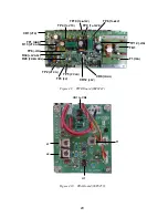
Matching Transformer
02S1138-1
CN5
J6
1
2
TRX Board 06P0241
RX Amplifier
TP3
Figure 3.4
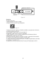
Procedures
To adjust receiver gain;
1. Set the frequency of the SG to 180 kHz.
2. Rotate R38 three steps from fully CCN position.
Figure 3.5
3. Unplug J6 and set the output level of the SG to 46 dBuV ( measured by the Volt-meter ).
4. Connect J6 and turn on CH-270.
5. Set the range to 1600 m, Gain to "10", and TVG to "0".
6. Adjust R57 to obtain 4.0
±
0.5 V at TP3 on TRX board.
7. Adjust transformers T1/T2/T3 so that the signal level at TP3 becomes maximum.
8. Readjust R57 to obtain 4.0
±
0.5 V at TP3.
9. Unplug J6 and set the output level of the SG to 53 dBuV. (measured by the Volt-meter)
10. Connect J6 and confirm that the signal level at TP3 is 9 VDC.
11. Unplug J6 and set the output level of the SG to 116 dBuV. (measured by the Volt-meter)
12. Set Gain to "0" and TVG to "10".
13. Adjust R70 so that the lowest level of the TVG curve at TP3 becomes 0.4
±
0.05 V.
Summary of Contents for CH-270
Page 1: ...COLOR SEARCHLIGHT SONAR CH 270...
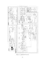
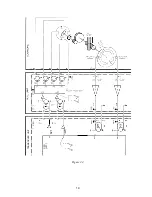
Page 13: ...10 58 59 6 6 DRV 06P0154 Hull Unit XDR Slip ring Figure 2 1 Signal Flow in Transmitter...
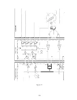
Page 14: ...11 Hull unit XDR Slip ring 6 6 59 58 Figure 2 2 Signal Flow in Receiver...
Page 19: ...16 Figure 2 5 TRANSCEIVER UNIT CPU J2 3 4 3 4 5 6 J10 5 6 7 8 CR16 U17 U34 191 R104 R105...
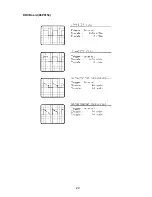
Page 23: ...20 DRV Board 06P0154...
Page 54: ......
Page 55: ......
Page 64: ......
Page 65: ......
Page 66: ......
Page 67: ......
Page 68: ......
Page 69: ......
Page 70: ......
Page 71: ......
Page 72: ......
Page 73: ......
Page 74: ......
Page 75: ......
Page 76: ......
Page 77: ......
Page 78: ......
Page 79: ......
Page 80: ......
Page 81: ......
Page 82: ......
Page 83: ......
Page 84: ......
Page 85: ......
Page 86: ......
Page 87: ......
Page 88: ......

