ASSEMBLY INSTRUCTIONS
Hardware
①
x 4 pcs
Page 8 of 11
Hardware
②
x 4 pcs
I.
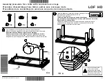
Insert the 4 cam connectors (#2)
into the holes of Part #E and #D.
Make sure each cam connector
(#2) is position correctly with the
arrow pointing to the small
drilled hole. Please refer to
“Cam Lock Fastener Assembly
Instructions” for detailed
instructions.
II.
Gently place Part #D and #E so
that the cam bolts/screws (#1)
are inside the cam connectors
(#2).
III. Use a Phillips screwdriver, to
tighten each cam connector (#2)
by turning right until it is locked
with the cam bolts/screws (#1).
The parts should fit snugly with
each other.
Ⓐ
Turn right (clockwise) to tighten
Turn right (clockwise) to tighten
Summary of Contents for Perry Round Geometric Coffee Table YNJ-129-6
Page 3: ...Page 3 of 11...
Page 5: ...Page 5 of 11 CAM LOCK FASTENER ASSEMBLY INSTRUCTIONS ly...
Page 6: ......


