Product Specification
Page 4 of 18
1303090MS01
LA-309 Controlled Atmosphere Infrared Furnace
April 15, 2009
4.0 PROCESS
SECTIONS
4.1
CONFIGURATION.
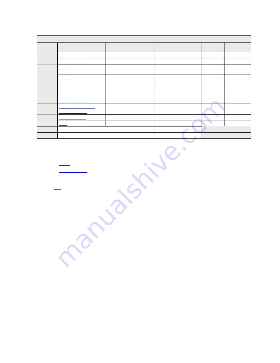
The equipment may be configured with options as follows:
Table 4-1. Furnace Configuration
Function
Name
Location
Length
Process
Gas
Temperature
(typ)
(optional)
Entrance Interface Roller
2.5 in
6.4 cm
none ambient
Product
Load
Entrance
15 in
38.1 cm
none ambient
- Baffle & Exhaust
Eductor
Entrance Barrier
15 in
38.1 cm
N
2
25-80°C
Heating Chamber 1
7.5 in
19.1 cm
N
2
80-300°C
Zone 2
Heating Chamber 1
15 in
38.1 cm
N
2
300-400°C
Zone 3
Heating Chamber 1
7.5 in
19.1 cm
N
2
300-400°C
IR
Furnace
Transition Tunnel /
Exhaust Eductor
Furnace Exit Barrier
15 in
38.1 cm
Cooling
Section
Closed Atmosphere
Cooling Tunnel
Cooling Exit Barrier
30 in
76.2 cm
N
2
25-150°C
Exit
15 in
38.1 cm
none ambient
Product
Unload
(optional)
Exit Interface Roller
2.5 in
6.4 cm
none ambient
Overall frame allowance
3 in
7.6 cm
Total
128 in
325.1 cm
4.2
PRODUCT LOAD.
The equipment shall provide access to the entrance of the heating
chambers via the following:
•
Entrance Interface Roller (optional)
•
4.3
IR FURNACE
. The IR furnace section shall consist of the following:
4.4
- Entrance Baffle & Exhaust Eductor. The entrance baffle section shall be housed inside an
aluminum shell lined with ceramic fiber insulation. The system shall include a metal air rake
to introduce a gas curtain above the belt. This gas curtain and a series of four equally spaced
hanging baffle gates shall serve to purge the chamber and prevent ambient air from entering the
heating section. A venturi-assisted exhaust stack shall draw gases from the entrance of zone 1,
across a drip tray and out of the furnace to prevent exhaust condensation from falling into the
entrance baffle. Proper operation of this system shall keep the furnace heating section clean.
4.5
Furnace Heating Section
. The heating section shall be comprised of 30 inch (76.2 cm) long
chambers; each chamber shall be partitioned into temperature controlled zones using ceramic
dividers. The dividers shall be configured with the smallest possible opening that can be made
to be consistent with the parts clearance specifications to assure very high thermal isolation
between the zones.
4.5.1.1
Chambers
. Each chamber shall be contained within an aluminum shell lined with
ceramic fiber insulation. Gas introduced into a plenum between the shell and the porous
insulation shall be heated as it passes through the insulation to enter the chamber at chamber
temperature. This method of gas distribution shall not affect the temperature profile, shall assist
in keeping the interior of the furnace clean and shall speed the cool down process when the
lamps are turned off
.
4.5.1.2
Control Zones.
The interior of the furnace chamber shall be partitioned into
controlled zones using ceramic dividers. The dividers shall be designed with the smallest
possible opening that can be made to be consistent with the parts clearance specifications to
assure very high thermal isolation between the zones. The chambers shall be divided into
zones as follows:
Summary of Contents for LA-309
Page 5: ...10 004 676 110000 v WARRANTY Warranty goes here ...
Page 6: ...vi LA 309 Owner s Manual ...
Page 12: ...Contents xii LA 309 Owner s Manual ...
Page 20: ...Section 1 1 8 LA 309 Owner s Manual ...
Page 68: ...Section 3 3 28 LA 309 Owner s Manual ...
Page 70: ...Section 4 4 2 LA 309 Owner s Manual ...
Page 72: ...Section 4 4 4 LA 309 Owner s Manual ...
Page 98: ...Section 5 5 2 LA 309 Owner s Manual ...
Page 100: ...Section 5 5 4 LA 309 Owner s Manual ...
Page 106: ...Section 5 5 10 LA 309 Owner s Manual ...
Page 108: ...Section 5 5 12 LA 309 Owner s Manual ...
Page 110: ...Section 5 5 14 LA 309 Owner s Manual ...
Page 112: ...Section 6 6 2 LA 309 Owner s Manual ...
Page 114: ......
Page 115: ......
Page 126: ...Section 7 1 Fiberfrax Cements MSDS 042006 Owner s Manual ...
Page 139: ...MSDS 2 Fiberfrax Duraboard MSDS 042006 MATERIAL SAFETY DATA SHEETS ...
Page 140: ...Section 7 2 Fiberfrax Duraboard MSDS 042006 Owner s Manual ...
Page 153: ...MSDS 3 Fiberfrax Fibers MSDS 042006 MATERIAL SAFETY DATA SHEETS ...
Page 154: ...Section 7 3 Fiberfrax Fibers MSDS 042006 Owner s Manual ...
Page 167: ...MSDS 4 Fiberfrax Papers MSDS 042006 MATERIAL SAFETY DATA SHEETS ...
Page 168: ...Section 7 4 Fiberfrax Papers MSDS 042006 Owner s Manual ...
Page 181: ...MSDS 5 Magnaform MSDS 050406 MATERIAL SAFETY DATA SHEETS ...
Page 182: ...Section 7 5 Magnaform MSDS 050406 Owner s Manual ...
Page 183: ......
Page 184: ......
Page 185: ...Section 7 6 RTU Silicone Red Hi Temp 042006 Owner s Manual ...
Page 186: ...MSDS 6 RTU Silicone Red Hi Temp 042006 MATERIAL SAFETY DATA SHEETS ...
Page 189: ...Section 7 7 Kaowool Insulation MSDS 050406 Owner s Manual ...
Page 190: ...MSDS 7 Kaowool Insulation MSDS 050406 MATERIAL SAFETY DATA SHEETS ...
Page 201: ...Material Safety Data Sheets 7 15 Notes ...
Page 202: ...Section 7 7 16 Owner s Manual ...
Page 204: ...Section 8 Owner s Manual ...
Page 206: ...Section 8 Owner s Manual ...
Page 212: ...iv Operation and Troubleshooting ...
Page 214: ...vi Operation and Troubleshooting ...
Page 224: ...Page 10 Operation and Troubleshooting ...
Page 231: ...9 1 Section 9 APPENDIX B 9 1 EC913 CALIBRATION REPORT 9 2 SERIES EC900 OXYGEN ANALYZERS ...
Page 232: ...Section 8 Owner s Manual ...
Page 233: ......
Page 234: ...Section 8 Owner s Manual ...
Page 279: ...Section 8 Owner s Manual ...
Page 281: ...MSDS MATERIAL SAFETY DATA SHEETS ...
Page 282: ...16 Notes ...


