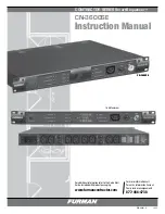
IT-Reference 7 - Owner’s Manual
- -
you about upgrades or other vital information.
Registering the product also upgrades your
warranty from one year to five years.
s
a F e t y
I
n F o r m at I o n
a n d
W
a r n I n g s
Please read and observe all of the safety and
operating instructions before the IT-Reference 7
is operated. Retain these instructions for future
reference.
Do not disassemble or modify in any way.
No user-serviceable parts inside
Keep away from moisture and avoid
excessive humidity
Do not allow liquids or foreign objects to
enter the unit Household lighting equipment
may not be connected to the IT-Reference
7 because their sockets are not designed
for use with symmetrical power and may
present a shock hazard. We recommend
that only audio, video and computer
processing equipment be connected to the
IT-Reference 7.
The IT-Reference 7 should be serviced by
qualified service personnel when:
The power supply cord or plug has been
frayed or cut.
Objects have fallen or liquid has spilled into
the unit.
The IT-Reference 7 has been exposed to
rain or other moisture.
The IT-Reference 7 does not appear to
operate normally, or exhibits a marked
change in performance.
The IT-Reference 7 has been dropped, or
the enclosure damaged.
◊
◊
◊
◊
◊
◊
◊
◊
The IT-Reference 7 requires that a safety ground
be present for proper operation. Any attempt
to operate the IT-Reference 7 without a safety
ground is considered improper operation and
will invalidate the warranty.
P
oWer
s
ource
The power source to which the IT-Reference
7 is connected should be adequate for use at
7 Amps. Typical household outlets will have a
current capacity of at least 10 - 15 amps.
P
lacement
The IT-Reference 7 is manufactured with
four rubber feet for placement on any table,
cabinet, shelf, or floor. These rubber feet may
be easily removed with a standard Philips screw
driver when rack mounting adjacent to other
components. Because of the IT-Reference 7’s
internal shielding, placement or proximity to
other components is not critical, and the IT-
Reference 7 does not produce any appreciable
heat under standard use. The IT- Reference 7
may also be rack mounted in a standard 19”
rack by attaching the rack ears. These rack ears
(contained within the plastic rack kit package)
mount flush with the back portion of the IT-
Reference 7’s front panel. They are attached
to the chassis by removing the () countersunk
screws on each forward-side of the chassis top
cover. Each rack ear is installed with (3) pan-
head Philips screws contained within the IT-
Reference 7 rack mounting kit. The third screw
used for each rack ear is for the center hole,
located towards the rear and aids in stabilizing
the unit when rack mounted.
c
o n n e c t I o n
ac c
able
r
outIng
Once the IT-Reference 7 is placed, its AC cord’s
female end must be plugged into the male IEC
Summary of Contents for IT-Reference 7
Page 1: ......


