background image

Purpose

This document is part of the user’s guide to the installation and configuration of bintec gateways run-

ning software release 7.2.10 or later. For up-to-the-minute information and instructions concerning the 

latest software release, you should always read our 

Release Notes

, especially when carrying out a 

software update to a later release level. The latest 

Release Notes

 can be found at 

www.funkwerk-

ec.com

.

Liability

While every effort has been made to ensure the accuracy of all information in this manual, Funkwerk 

Enterprise Communications GmbH cannot assume liability to any party for any loss or damage caused 

by errors or omissions or by statements of any kind in this document and is only liable within the scope 

of its terms of sale and delivery.

The information in this manual is subject to change without notice. Additional information, changes and 

Release Notes

 for bintec gateways can be found at 

www.funkwerk-ec.com

.

As multiprotocol gateways, bintec gateways set up WAN connections in accordance with the system 

configuration. To prevent unintentional charges accumulating, the operation of the product should be 

carefully monitored. Funkwerk Enterprise Communications GmbH accepts no liability for loss of data, 

unintentional connection costs and damages resulting from unsupervised operation of the product.

Trademarks

bintec and the bintec logo are registered trademarks of Funkwerk Enterprise Communications GmbH.

Other product names and trademarks mentioned are usually the property of the respective companies 

and manufacturers.

Copyright

All rights are reserved. No part of this publication may be reproduced or transmitted in any form or by 

any means – graphic, electronic, or mechanical – including photocopying, recording in any medium, 

taping, or storage in information retrieval systems, without the prior written permission of Funkwerk En-

terprise Communications GmbH. Adaptation and especially translation of the document is inadmissible 

without the prior consent of Funkwerk Enterprise Communications GmbH.

Guidelines and standards

bintec gateways comply with the following guidelines and standards:

R&TTE Directive 1999/5/EG

CE marking for all EU countries and Switzerland

You will find detailed information in the Declarations of Conformity at 

www.funkwerk-ec.com

.

How to reach Funkwerk 

Enterprise Communications 

GmbH

Funkwerk Enterprise Communications GmbH


Suedwestpark 94


D-90449 Nuremberg


Germany

Telephone: +49 180 300 9191 0


Fax: +49 180 300 9193 0


Internet: 

www.funkwerk-ec.com

Bintec France


6/8 Avenue de la Grande Lande


F-33174 Gradignan


France

Telephone: +33 5 57 35 63 00


Fax: +33 5 56 89 14 05


Internet: www.bintec.fr

Summary of Contents for bintec R230a

Page 1: ...Copyright April 26 2006 Funkwerk Enterprise Communications GmbH Version 2 0 User s Guide bintec R230a R230aw R232b R232bw System ...

Page 2: ...s of data unintentional connection costs and damages resulting from unsupervised operation of the product Trademarks bintec and the bintec logo are registered trademarks of Funkwerk Enterprise Communications GmbH Other product names and trademarks mentioned are usually the property of the respective companies and manufacturers Copyright All rights are reserved No part of this publication may be re...

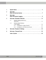
Page 3: ...rnal System Logging 9 4 Submenu Schedule Monitor 13 4 1 Submenu Keepalive Monitoring Hosts Ifc 13 4 2 Submenu Event Scheduler Time SNMP 18 4 2 1 Configuration of triggers Events 19 4 2 2 Configuration of the Action Command 26 5 Submenu Password Settings 33 6 Submenu Time and Date 35 Index System 39 ...

Page 4: ...2 bintec User s Guide System ...

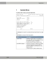
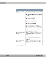
Page 5: ... Message Level for the Syslog Table info Maximum Number of Syslog Entries 20 Maximum Number of Acctlog Entries 20 External Activity Monitor External System Logging Schedule Monitor Password Settings Time and Date SAVE CANCEL Field Description System Name Defines the system name of your gateway is also used as PPP host name Appears as input prompt when logging in to the device The device type is en...

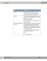
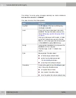
Page 6: ...rator for example Default value BINTEC Is shown for example on the HTML system information page Syslog Output on Serial Console Enables the display of syslog messages on the PC connected to the serial interface of the gateway Use this setting only if you make a fault analysis as a very large output over the serial console adversely affects the throughput of the other interfaces You should normally...

Page 7: ...ebug messages lowest priority Syslog messages are only recorded internally if they have a higher or identical priority to that indicated i e all messages generated are recorded at syslog level debug Maximum Number of Sys log Entries Maximum number of syslog messages saved internally in the gateway possible values 0 1000 Default value 20 You can show the saved messages in the Setup Tool under MONIT...

Page 8: ...1 6 bintec User s Guide System System Menu ...

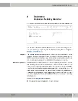
Page 9: ...ion A Status Daemon collects information about the gateway and transfers it in the form of UDP packets to the broadcast address of the first LAN interface default setting or to an explicitly entered IP address One packet is sent per time inter val which can be adjusted individually to values from 1 60 seconds Up to 100 physical and virtual interfaces can be monitored provided the packet size of 4 ...

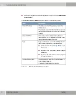
Page 10: ... means that the broadcast address of the first LAN interface is used Client UDP Port Port number for the bintec Activity Monitor default value 2107 registered by IANA Inter net Assigned Numbers Authority Type Type of information sent in the UDP packets to the Windows application Possible values off Deactivates the Activity Monitor de fault value physical Only information about physical interfaces ...

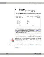
Page 11: ...e passed to one or more external PCs for storage and processing e g to the system administrator s PC The syslog messages saved internally on the gateway are lost on a restart Syslog Daemon All Unix operating systems support the recording of syslog messages For Win dows PCs the Syslog Daemon included in the DIME Tools can record the data and distribute to various files depending on the contents see...

Page 12: ...e 5 Only syslog messages with the same or higher priority than indicated are passed to the LOG HOST i e all the messages created are passed to the LOG HOST in syslog LEVEL Debug Facility Syslog facility at LOG HOST Only required if the LOG HOST is a Unix computer Possible values local0 7 default value local0 Type Message type Possible values all All messages default value system Syslog messages ex...

Page 13: ...em bintec User s Guide 11 Submenu External System Logging 3 Table 3 1 EXTERNAL SYSTEM LOGGING menu fields Method Protocol for sending syslog messages Possible values udp default value tcp Field Description ...

Page 14: ...3 12 bintec User s Guide System Submenu External System Logging ...

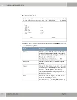
Page 15: ...ALIVE MONITORING menu contains settings for the Keepalive Monitoring feature Keepalive Monitoring cannot be configured in the gateway for WAN partners that are authenticated via a RADIUS server SYSTEM SCHEDULE MONITOR KEEPALIVE MONITORING lists the hosts and interfaces monitored by Keepalive Monitoring The reachability of the hosts is listed under STATE alive if the host was reachable on the last ...

Page 16: ...scription Group Defines a group of hosts whose reachability is to be monitored by the gateway Each host to be monitored is assigned to a group A total of 256 groups can be created Possible values 0 default value 255 IP Address Defines a host that is to be monitored by the gateway Interval Defines the time interval in seconds to be used for checking the reachability of hosts Possible values 1 65536...

Page 17: ... admin status is set to up up Interfaces are activated The status of the interfaces is set to the original value again when at least one host in a group can be reached again Note DOWNACTION must be configured identi cally within a group FirstIfIndex Defines the first interface of an interface range in the gateway for which the action down or up defined under DOWNACTION is to be exe cuted Possible ...

Page 18: ...ACTION is to be executed Default value 4999 If you set FIRSTIFINDEX 10001 and RANGE 1 only the interface with the index 10001 is affected If you set FIRSTIFINDEX 10001 and RANGE 19 the interfaces with the indices 10001 to 10020 are affected VR232bw Setup Tool Funkwerk Enterprise Communications GmbH SYSTEM KEEPALIVE MONITORING ADD Interface Monitoring MyGateway Interface 0 Trigger down Action none ...

Page 19: ...X can be determined for example with the command ifstat Default value 0 Trigger Defines the status of INTERFACE which initiates a certain ACTION Possible values down Interface is deactivated default val ue up Interface is activated Action Defines the action that is to follow the status defined in TRIGGER The action is executed on the interface range from FIRSTIFINDEX and FIRSTIFINDEX RANGE Possibl...

Page 20: ...teway for which the action down or up defined under DOWNACTION is to be exe cuted Possible values 100 65536 Default value 10001 Interfaces with indices from 10001 to 14999 are provided for dialup connections to WAN part ners You can find the indices of the interfaces with for example the command ifstat Range Defines the range of interfaces in the gateway for which the action defined under ACTION i...

Page 21: ...hains so that complex conditions for initiating an action can also be created To be able to use the Event Scheduler function the date on the gateway must be at least January 1 2000 4 2 1 Configuration of triggers Events The SYSTEM SCHEDULE MONITOR EVENT SCHEDULER TIME SNMP SCHEDULE EVENTS menu displays a list of all already configured events New events are added with ADD existing entries are modif...

Page 22: ...ex 1 Description NextIndex none Type time Condition daily Start time hh mm End time hh mm Status notavail SAVE CANCEL R232bw Setup Tool Funkwerk Enterprise Communications GmbH SYSTEM SCHEDULED SCHED_EVT ADD Scheduler Events MyGateway Index 1 Description NextIndex none Type value Monitored event user defined Table Variable Index variable Index value Condition range Compare value End value Status no...

Page 23: ...ion for the event The maximum length of the entry is 30 characters NextIndex Here you select from the existing entries the entry that is to follow the current entry in an event chain if applicable The entries in an event chain form a complex condition for an action to be executed How the event chain leads to an action is configured in the SYSTEM SCHEDULE MONITOR EVENT SCHEDULER TIME SNMP SCHEDULE ...

Page 24: ...ding on the total connection duration of a ppp interface WAN interface total RX traffic The event is defined depending on the total received data volumn of a ppp interface WAN interface total TX traffic The event is defined depending on the total sent data volumn of a ppp interface Table Only for MONITORED EVENT user defined Here you enter the name of the MIB table con taining the MIB variable tha...

Page 25: ...s index to clearly define one specific data record in the table e g ConnIfIndex The combination of INDEX VARIABLE and INDEX VALUE defines the specific table entry Index value Only for MONITORED EVENT user defined Here you enter the value of the INDEX VARIABLE that clearly defines the data record that con tains the required trigger variable e g 10001 for CONNIFINDEX Field Description ...

Page 26: ...turdays and Sundays only day 1 31 The trigger becomes repeat edly active on a certain day of each month For TYPE value range The trigger becomes active if the value of the variable is in the range of COMPARE VALUE and END VALUE default val ue greater The trigger becomes active if the value of the variable exceeds COMPARE VALUE equal The trigger becomes active if the value of the variable is COMPAR...

Page 27: ...or CONDITION range The end value of the range of values Start time hh mm Only for TYPE time Here you enter the time starting at which the trigger is to be activated Activation is executed with the next schedule intervall End time hh mm Only for TYPE time Here you enter the time starting at which the trigger is to be deactivated Deactivation is executed with the next schedule intervall If no END TI...

Page 28: ...eady configured actions Entries are added or modified in the SYSTEM SCHEDULE MONITOR EVENT SCHEDULER TIME SNMP SCHEDULE COMMANDS ADD EDIT menu Status This field cannot be edited and shows the sta tus of the trigger Possible values error An error has occurred the configura tion of the trigger is not consistent notavail The status cannot be determined e g if the scheduler has not yet been acti vated...

Page 29: ... Index none Eventlist Condition all Execute command user defined Table Variable Index variable Index value Set value active value inactive Notify all Status notavail Last Change 01 01 1970 0 00 00 SAVE CANCEL R232bw Setup Tool Funkwerk Enterprise Communications GmbH SYSTEM SCHEDULED SCHED_CMD ADD Scheduler Commands MyGateway Index 1 Description Mode enable 1 Event Index none Eventlist Condition al...

Page 30: ... SCHEDULE MONITOR EVENT SCHEDULER TIME SNMP SCHEDULE COMMANDS It should be unique Possible settings 1 to 65535 Description Here you enter the desired description for the action The maximum length of the entry is 30 characters Mode Here you select if the configured action is to be enabled or not Possible settings enable default value action is enabled disable action is disabled 1 Event Index Here y...

Page 31: ...ent chain is active one_not The action is to be active if at least one of the events of the event chain is not active Execute command Here you define the action that is executed by a trigger Possible settings disable interface The interface set in the INTERFACE field is deactivated its ADMINSTATUS is set to down enable interface The interface set in the INTERFACE field is activated its ADMINSTATUS...

Page 32: ... to clearly define one specific data record in the table e g Index The combination of INDEX VARIABLE and INDEX VALUE defines the specific table entry Index value Only for EXECUTE COMMAND user defined Here you enter the value of the INDEX VARIABLE that clearly defines the data record that con tains the required trigger variable e g 10001 for INDEX Set value active Only for EXECUTE COMMAND user defi...

Page 33: ...are gener ated none No syslog messages or traps are generated To generate SNMP traps you must if applica ble generate a respective entry in the BIBOADMUSRTRAPTABLE Status Shows the status of the action This field cannot be edited Possible values active The action is currently active inactive The action is inactive notavail The status cannot be determined e g if the scheduler is not activated or no...

Page 34: ...4 32 bintec User s Guide System Submenu Schedule Monitor ...

Page 35: ...erk Enterprise Communications GmbH SYSTEM PASSWORDS Change System Passwords MyGateway admin Login Password SNMP Community read Login Password SNMP Community write Login Password SNMP Community HTTP Server Password Activity Monitor Password SAVE CANCEL Field Description admin Login Pass word SNMP Community Password for user name admin read Login Pass word SNMP Community Password for user name read ...

Page 36: ... with the same user name and password As long as the password remains unchanged they are not protected against unau thorized use Change the password to prevent unauthorized access to the gateway As long as the password remains unchanged the following warning appears on logging in Password not changed ...

Page 37: ...ATE To assure that your gateway uses the correct current time it is recommended to configure time servers R232bw Setup Tool Funkwerk Enterprise Communications GmbH SYSTEM TIME Control System Time and Date MyGateway Current System Time Wed 2005 Feb 28 19 19 37 setby None Change System Time 2005 Feb 28 19 19 17 CHANGE Time Update Interval 86400 Seconds Update System Time from ISDN disabled System Ti...

Page 38: ... Here you can choose whether the time informa tion received at the beginning of an incoming ISDN connection is used to update the system time This option is used as long as a time update has been received from a time server since boot time Available values are enabled and disabled the default value is disabled System Time Offset from GMT Here you enter the offset in seconds between system time and...

Page 39: ...d for querying the time server Possible values SNTP This server uses the Simple Net work Time Protocol with UDP port 123 disabled This time server is currently not used for time retrieval TIME UDP This server uses the Time ser vice with UDP port 37 TIME TCP This server uses the Time ser vice with TCP port 37 Field Description ...

Page 40: ...6 38 bintec User s Guide System Submenu Time and Date ...

Page 41: ...hange System Time 36 CLID 13 Client IP address 8 Client UDP port 8 Compare value 25 Condition 24 Contact 4 Current System Time 36 D Description 21 28 DownAction 15 E End time 25 End value 25 Event protocol 9 Eventlist condition 29 Execute command 29 External Activity Monitor 7 External system logging 9 F Facility 10 FirstIfIndex 15 18 G Group 14 ...

Page 42: ...3 Interval 14 IP address 14 K Keepalive Monitoring 13 L LAN 13 Last change 31 Level 10 Local PPP ID default 3 Location 4 Log host 9 10 M Maximum Number of Acctlog Entries 5 Maximum number of syslog entries 5 Message level for the syslog table 5 Method 11 Mode 28 Monitored event 22 N Name Address 36 Next index 21 Notify 31 ...

Page 43: ...ue active 30 Source IP 15 Start time 25 Status 26 31 Subsystems 9 Syslog messages 9 Syslog output on serial console 4 System name 3 System time 35 Accounting 35 Automatic 35 Manual 35 System Time Offset from GMT 36 T Table 22 30 Time and date 35 Time Update Interval 36 Timestamp 10 Trials 14 Trigger 17 Type 8 10 21 U Update interval 8 Update System Time from ISDN 36 ...

Page 44: ...42 bintec User s Guide System V Value inactive 30 Variable 22 30 ...

Reviews: