


2-4
LTVN_ISP
Safety Check after Servicing
Examine the area surrounding the repaired location for damage or deterioration. Observe that screws, parts and
wires have been returned to original positions. Afterwards, perform the following tests and confirm the specified
values in order to verify compliance with safety standards.
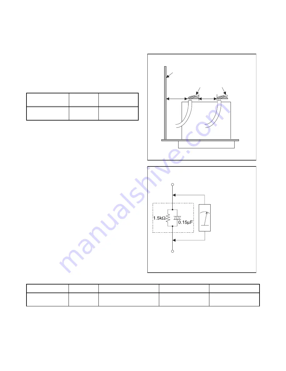
1. Clearance Distance
When replacing primary circuit components, confirm
specified clearance distance (d) and (d') between
soldered terminals, and between terminals and
surrounding metallic parts. (See Fig. 1)
Table 1: Ratings for selected area
Note:
This table is unofficial and for reference only. Be
sure to confirm the precise values.
2. Leakage Current Test
Confirm the specified (or lower) leakage current
between B (earth ground, power cord plug prongs) and
externally exposed accessible parts (RF terminals,
antenna terminals, video and audio input and output
terminals, microphone jacks, earphone jacks, etc.) is
lower than or equal to the specified value in the table
below.
Measuring Method: (Power ON)
Insert load Z between B (earth ground, power cord plug
prongs) and exposed accessible parts. Use an AC
voltmeter to measure across both terminals of load Z.
See Fig. 2 and following table.
Table 2: Leakage current ratings for selected areas
Note:
This table is unofficial and for reference only. Be sure to confirm the precise values.
AC Line Voltage
Region
Clearance
Distance (d), (d’)
110 to 130 V
U.S.A. or
Canada
≥
3.2 mm
(0.126 inches)
AC Line Voltage
Region
Load Z
Leakage Current (i)
Earth Ground (B) to:
110 to 130 V
U.S.A. or
Canada
0.15
µ
F CAP. & 1.5 k
Ω
RES. Connected in parallel
i
≤
0.5 mA rms
Exposed accessible
parts
Chassis or Secondary Conductor
Primary Circuit
Fig. 1
d'
d
AC Voltmeter
(High Impedance)
Exposed Accessible Part
B
Earth Ground
Power Cord Plug Prongs
Z
Fig. 2
Summary of Contents for FL10.1
Page 14: ...4 2 FL10 1DC 2 Rear Cabinet S 1 1 Stand Assembly S 2 S 2 S 5 S 2 S 4 S 3 S 2 S 2 S 2 Fig D1...
Page 39: ...10 3 FL10 1SCM1 Main 1 Schematic Diagram...
Page 40: ...10 4 FL10 1SCM2 Main 2 Schematic Diagram...
Page 41: ...10 5 FL10 1SCM3 Main 3 Junction B Schematic Diagram...
Page 43: ...10 7 FL10 1SCJ Jack Junction C Schematic Diagram...
Page 44: ...10 8 FL10 1SCF Function Junction A Schematic Diagram...


