


5-2
FL10.2EA
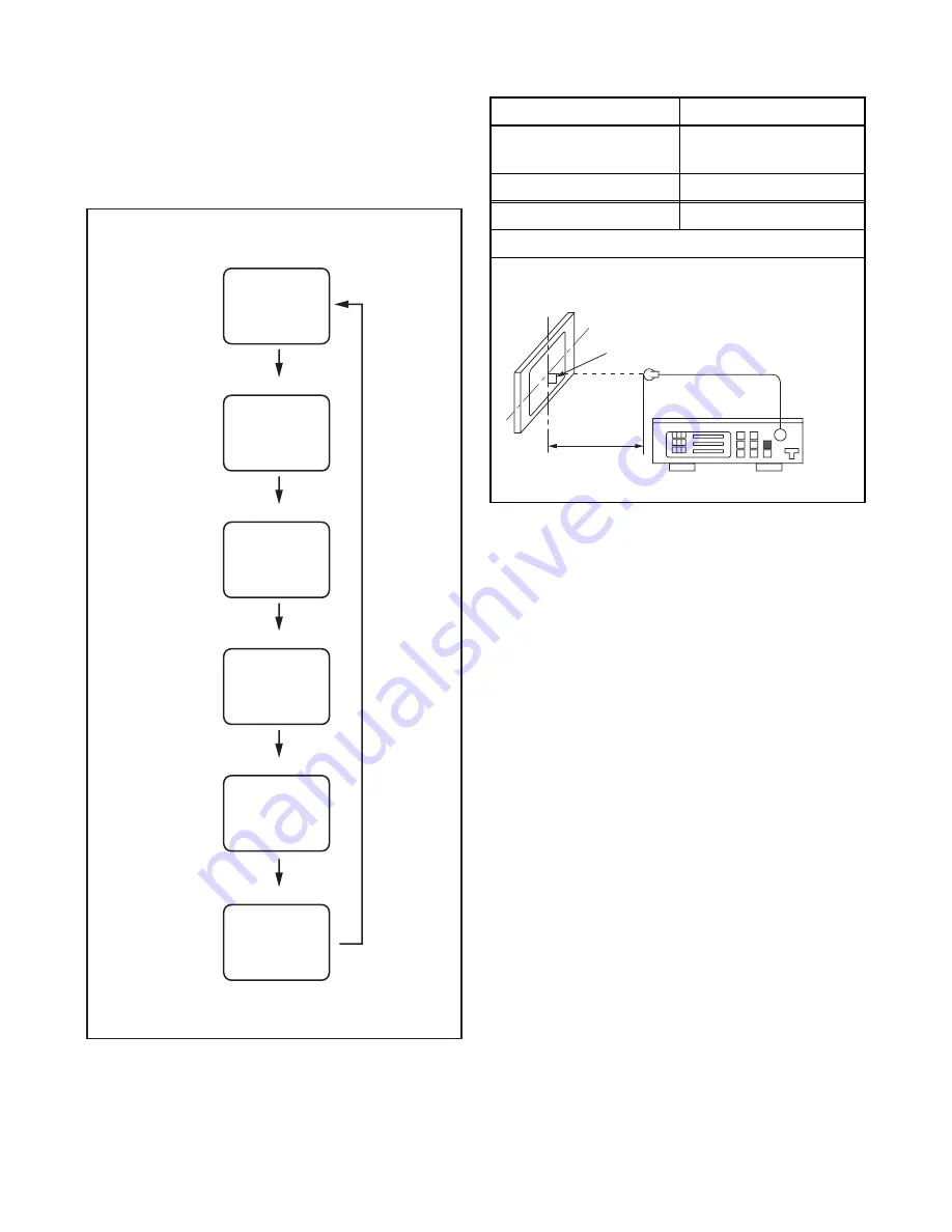
1. Purity Check Mode
This mode cycles through full-screen displays of red,
green, blue, and white to check for non-active pixels.
1. Enter the Service mode.
2. Each time pressing [7] button on the remote
control unit, the display changes as follows.
3. To cancel or to exit from the Purity Check Mode,
press [PREV CH] button.
2. VCOM Adjustment
1. Operate the unit for more than 20 minutes.
2. Set the color analyzer and bring the optical
receptor to the center on the LCD-Panel surface
after zero point calibration as shown above.
Note:
The optical receptor must be set
perpendicularly to the LCD Panel surface.
3. Enter the Service mode.
4. Press [3] button on the remote control unit.
5. Press [CH
X
/
Y
] buttons on the remote control unit
so that the color analyzer value becomes
minimum.
6. To cancel or to exit from the VCOM Adjustment,
press [PREV CH] button.
[7] button
Note:
When entering this mode, the default setting is White mode.
Purity Check Mode
[7] button
Red mode
Green mode
Blue mode
Black mode
[7] button
White mode
[7] button
[7] button
White 20% mode
[7] button
Test Point
Adj. Point
Screen
[CH
X
/
Y
]
buttons
M. EQ.
Spec.
Color analyzer
See below
Figure
Color Analyzer
To avoid interference from ambinent
light, this adjustment should be
performed in a dark room.
L = 3 cm
Perpendicularity
Summary of Contents for FL10.1
Page 14: ...4 2 FL10 1DC 2 Rear Cabinet S 1 1 Stand Assembly S 2 S 2 S 5 S 2 S 4 S 3 S 2 S 2 S 2 Fig D1...
Page 39: ...10 3 FL10 1SCM1 Main 1 Schematic Diagram...
Page 40: ...10 4 FL10 1SCM2 Main 2 Schematic Diagram...
Page 41: ...10 5 FL10 1SCM3 Main 3 Junction B Schematic Diagram...
Page 43: ...10 7 FL10 1SCJ Jack Junction C Schematic Diagram...
Page 44: ...10 8 FL10 1SCF Function Junction A Schematic Diagram...


