


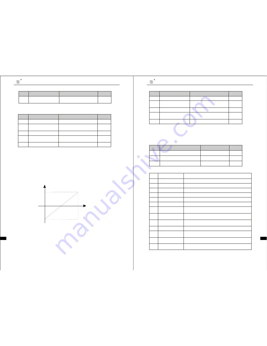
Above function code s define the relationship between analog i nput voltage and the setting value that
analog input is corresponding to. When the ana log input voltage exceeds the range of the set ma ximum or
minimum input, the beyond porti on should be c alculated with maxi mum input or minimum i nput.
When analog input is amperage input, 0mA-20mA is corresponding to 0V-10V.
For different applications, t he corresponding nominal value of analog sett ing 100.0% is different. For
details, pleas e refer t o each application description.
Following figures shows several sett ings. Note:
lower limit must be less or equal to
uppe r limit.
VI
VI
10V
0V
(20mA)
C I
(
)
0m A
100.0%
-10 0. 0%
f requency setting ,torque ,PID setting,PID feed back
C ORRESPONDING SETTING
F ig. 6-12 Relationship between analog input and s etti ng value
VI input filt eri ng t ime determines anal og input sensi ti veness . Increasi ng t his parameter, i n order to
prevent mal funct ion caused by interference to the a nalog, can s trengthen the anti-interference ability,
but reduce the analog input sensitiveness.
Open c oll ector output functions are indicated as foll owi ng t able:
Function
Code
Nam e
Se tting Rang e
Defa ult
Value
F2.19
1
F2.20
F2.21
3
0~10
0~10
Mo1output sel ection
Re lay output selection
Setting
Value
0
1
2
3
4
5
6
7
8
9
10
~
Description
Function
Lower limit frequency
reaches
Upper limit frequency
reaches
Null speed operation
Zero Output
Inverter is running forward
Inverter is running reverse
Fault output
FDT reaches
Reserved
Frequency reaches
When the operating frequency reaches the lower frequency limit,
output ON signal.
When the operating frequency reaches the upper frequency limit,
output ON signal.
When the inverter output frequency is less than the starting
frequency, output ON signal
Output terminal has no function
ON signal Indicates the inverter is running forward with output frequency.
ON signal Indicates the inverter is running reverse with output frequency.
Once inverter fault happens, output ON signal
please refer to the detail description of function code F4.13,F4.14
please refer to the detail description of function code F4.15
Reserved
Cha pter 6 Pa ram eter Descri ption
DZB Series
Cha pter 6 Para meter Descr iption
DZB Series
CIfunction settings a re similar to VI setting met hod.
DZB Series i nverter provides 2 paths of analog input port.
DZB Series i nverter standard uni t has two multifunction digi tal output terminal , one (or t wo)
mult ifunc ti on relay output t ermi nals and one analog output t ermi nal.
F2.17
CI upper limit
corresp onding setting
-100.0%
100 .0%
~
10 0.0%
F2.18
CI input filter ing time
0.0s
10.0 s
~
0.1s
F2.14
CI lower lim it
0.0V
10.0V
~
0.0 V
F2.15
CI lower lim it
corre sponding setting
-100. 0%
100.0%
~
0.0%
F2.16
CIu pper limi t
0.0V
10.0V
~
10.0V
Funct ion
Code
Name
S ettin g Ran ge
Defa ult
Value
F2.09
VI lowe r limit
0.0V
10.0V
~
0.0V
F2.10
VI lowe r limit
corre sponding setti ng
-100.0%
100.0%
~
0.0%
F2.11
VI upper limi t
0.0V
10.0V
~
10.0V
F2.12
VI upper lim it
corre sponding setti ng
-100.0%
100.0%
~
100.0%
F2.13
VI input filtering tim e
0.0s
10.0s
~
0.1s
Function
Code
Name
Se tt ing Rang e
Defau lt
Value
Terminal UP/DOWN regul at es t he change rate of frequenc y s et ti ng.
F2.08
UP/DOWN frequency
increm ent variable rate
0.0 1
99.99Hz/s
~
0.50Hz /s
Functio n
Cod e
Name
Setting Range
Default
Value
11
12
13
high pressure reaches
detection(NC)
Pressure reaches at the F7.12 high pressure setting,NO output indication.
low pressure reaches
detection(NC)
high pressure reaches
detection(NO)
Pressure reaches at the F7.12 low pressure setting,NC output indication.
Pressure reaches at the F7.13 high pressure setting,NC output indication.
Reserv ed
-49-
-5 0-
BLUE ELEPHANT BLUE ELEPHANT BLUE ELEPHANT BLUE ELEPHANT
BLUE ELEPHANT BLUE ELEPHANT BLUE ELEPHANT BLUE ELEPHANT
BLUE ELEPHANT BLUE ELEPHANT BLUE ELEPHANT BLUE ELEPHANT
BLUE ELEPHANT BLUE ELEPHANT BLUE ELEPHANT BLUE ELEPHANT
BLUE ELEPHANT BLUE ELEPHANT BLUE ELEPHANT BLUE ELEPHANT
BLUE ELEPHANT BLUE ELEPHANT BLUE ELEPHANT BLUE ELEPHANT


