


10
11
KNOW YOUR PRODUCT
OPERATION
OPERATION (cont.)
WARNING!
Read and understand the warnings before setup and
testing.
3.
To disconnect first remove the black negative terminal clamp (3) from the
negative ( – ) pole of your vehicle battery.
4.
Remove the red positive terminal clamp (2) from the positive ( + ) pole of the
vehicle battery.
+
-
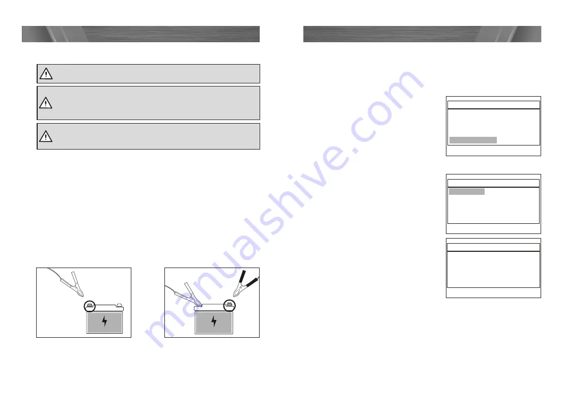
Fig. 1
Connecting and disconnecting from a vehicle battery
Before testing make sure the battery terminals are really clean as grease and dust
could lead to errors in the test results. The battery MUST be disconnected prior
to cleaning. Check the battery and connections for any cracks or damage before
proceeding with cleaning and testing. To help ensure a good connection of the
battery terminal clamps, clean the battery terminals with a solution of baking soda
and water, and wipe the battery terminals with a cloth to remove any dirt and
grease.
If the battery is still fitted to a motor vehicle, make sure that all the electronics are
turned OFF, and that the ignition is turned OFF
1.
To connect first attach the red positive terminal clamp (2) to the positive (+) pole
on your vehicle 12V battery (fig. 1).
2.
Connect the black negative terminal clamp (3) to the negative (–) pole on your
vehicle 12V battery (fig. 2). Ensure both clamps are secure.
WARNING!
Ensure the power cord is uncoiled and fully
extended to avoid overheating the power cord. Ensure that is
does not get tangled or caught in any rotating parts within the
engine compartment of the vehicle.
WARNING!
Check cord and clamp for damage before every use. Do
not use if cord or clamp if insulation is missing or damaged and wire is
exposed.
+
-
Fig. 2
System setup
1.
Connect the battery tester to the battery, following the instructions specified in
the
"Connecting and disconnecting from a vehicle battery"
section.
2.
The LCD screen (1) will display the tester model, version and battery voltage,
press the enter button (7) to the next step.
3.
From the Main Menu, using the up button
(8) and down buttons (6) select System
Setup (fig. 3) and press enter button (7).
•
Language
1.
From the System Setup menu (fig. 4),
use the up and down buttons to select
Language and press enter button (7).
2.
From the Language menu, use the up
and down buttons to select the desired
language from the options available (fig. 5).
3.
Press enter button (7) to save your selection
and return to previous menu.
Main Menu
1. Battery Test
2. Cranking Test
3. Charging Test
4. Review Data
5. Print
6. System Setup
System Setup
1. Language
2. Fn settings
3. Contrast
4. Tool information
Language
1. English
2. German
3. Spanish
4. French
5. Italian
6. Dutch
System Setup
1. Language
2. Fn settings
3. Contrast
4. Tool information
System Setup
1. Language
2. Fn settings
3. Contrast
4. Tool information
System Setup
1. Language
2. Fn settings
3. Contrast
4. Tool information
Fn Setting
1. Voltmeter
2. Quick Test Mode
Contrast
50
Tool Information
Software Version 1.04
Hardware Version 1.01
Fig. 3
Main Menu
1. Battery Test
2. Cranking Test
3. Charging Test
4. Review Data
5. Print
6. System Setup
System Setup
1. Language
2. Fn settings
3. Contrast
4. Tool information
Language
1. English
2. German
3. Spanish
4. French
5. Italian
6. Dutch
System Setup
1. Language
2. Fn settings
3. Contrast
4. Tool information
System Setup
1. Language
2. Fn settings
3. Contrast
4. Tool information
System Setup
1. Language
2. Fn settings
3. Contrast
4. Tool information
Fn Setting
1. Voltmeter
2. Quick Test Mode
Contrast
50
Tool Information
Software Version 1.04
Hardware Version 1.01
Fig. 4
Main Menu
1. Battery Test
2. Cranking Test
3. Charging Test
4. Review Data
5. Print
6. System Setup
System Setup
1. Language
2. Fn settings
3. Contrast
4. Tool information
Language
1. English
2. German
3. Spanish
4. French
5. Italian
6. Dutch
System Setup
1. Language
2. Fn settings
3. Contrast
4. Tool information
System Setup
1. Language
2. Fn settings
3. Contrast
4. Tool information
System Setup
1. Language
2. Fn settings
3. Contrast
4. Tool information
Fn Setting
1. Voltmeter
2. Quick Test Mode
Contrast
50
Tool Information
Software Version 1.04
Hardware Version 1.01
Fig. 5


