Full Boar FBBS-750 Instruction Manual Download Page 22

22

KNOW YOUR PRODUCT

Advanced blade tracking:

Most tracking adjustments can be done by simply adjusting the top 

wheel tracking knob as the lower wheel comes correctly adjusted 

from the factory. However there may come a time when adjustment is 

necessary such as if the blade keeps falling off the drive wheels.

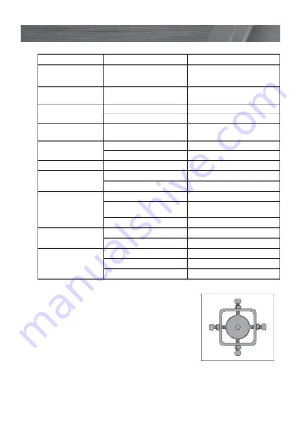
At the back of the unit you will find 4 screws that allows fine 

adjustment to the lower pulley tacking. The upper and lower screws 

adjust the vertical angle and the left and right screws adjust the 

horizontal angle. If the lower wheel tracking is out, only adjust the 

upper and lower screws. However if the wheels keep throwing the 

blade, you will have to adjust horizontal angle using the left and 

right screws. When adjusting the angle ensure you only make small 

adjustments, being careful to tighten and loosen in the direction you wish to align. For example, 

loosening the left screw then tightening the right screw. This is to ensure there is no movement in 

the wheels angle during operation. Be sure all adjustment screws are tight before use and you have 

manually spun the wheels by hand to check the alignment.

TROUBLESHOOTING

Problem

Cause

Remedy

Bandsaw is not 

working

No power supplied

Make sure the power plug is 

connected and power outlet is in 

working order

Cannot adjust 

tracking

Tracking lock knob is on

Unlock the tracking lock by turning 

the tracking lock knob anti-clockwise

Premature and 

excessive tooth wear

Feed Pressure too high

Slow down feed rate

Guide hitting teeth alignment

Readjust blade tracking and guides

Finished surface too 

rough

Feed rate too high

Slow down feed rate

Premature blade 

breakage

Band tension too high

Readjust blade tension

Excessive feed pressure

Slow down feed rate

Cutting rate too slow

Damaged or worn blade

Replace blade

Gullets loaded with 

chips

Speed too slow

Use faster speed

Chip brush not working properly

Clean or replace brushes

Belly shaped cuts

Improper blade tension

Readjust blade tension

Guide arm is too far from work 

piece

Move guide arm closer to work piece

Excessive feed force

Use less feed force

Band stalls in work

Feed pressure too great

Use less feed force

Improper blade tension

Readjust blade tension

Blade vibration

Guides poorly adjusted

Readjust blade tracking and guides

Blades tension too low

Readjust blade tension

Work piece not properly secured

Secure work piece properly

Summary of Contents for FBBS-750

Page 1: ...lure to follow the warnings and instructions may result in electric shock fire and or serious injury Save all warnings and instructions for future reference 01 18 305MM BANDSAW WITH STAND INSTRUCTION...

Page 2: ...le 495 x 390 mm Table tiltable 0 45 Tool weight 65 kg SPECIFICATIONS MODEL NO FBBS 750 KNOW YOUR PRODUCT a Small washer b Small spring washer c Small nut d Short hex bolt e Long hex bolt f Long bolt g...

Page 3: ...ock 11 Guard adjustment knob 12 Guard adjustment lock 13 Upper guides 14 Blade 15 Saw table 16 Rip fence ruler 17 Lower guides 18 Locker door lock 19 Drive belt tensioning crank 20 Stabilising leg 21...

Page 4: ...CTION Page 05 SAFETY INSTRUCTIONS Page 05 STAND ASSEMBLY Page 09 SETUP PREPARATION Page 11 SAW ASSEMBLY Page 15 OPERATION Page 17 MAINTENANCE Page 20 TROUBLE SHOOTING Page 22 DESCRIPTION OF SYMBOLS Pa...

Page 5: ...responds to the voltage on the rating plate Note The supply of 230V and 240V is interchangeable for Australia and New Zealand The power supply for this product should be protected by a residual curren...

Page 6: ...d Never use the cord for carrying pulling or unplugging the power tool Keep cord away from heat oil sharp edges or moving parts Damaged or entangled cords increase the risk of electric shock e When op...

Page 7: ...justments changing accessories or storing power tools Such preventive safety measures reduce the risk of starting the power tool accidentally d Store idle power tools out of the reach of children and...

Page 8: ...be cut Take care that the selection of the saw band and the speed depends on the material to be cut Do not touch moving parts with your fingers or hands Ensure that you have tensioned the blade prior...

Page 9: ...other Place one long upper support in between the legs and align the bolt holes 2 The long upper support should have its lip on the high side facing up Before bolting the long upper support ensure tha...

Page 10: ...e the frame 9 Align the holes of each opposing member If the holes are misaligned and cannot be aligned by hand use of a soft hammer to tap the members together is recommended Bolts and nuts can be in...

Page 11: ...Before adjusting the tracking of the blade the blade should move approx 8 10mm when applying pressure 4 If the measurement is greater than 8 10mm turn the blade tension knob clockwise to increase the...

Page 12: ...position of the blade 5 If the blade runs towards the front of the upper wheel the blade tracking adjustment must be turned clockwise direction 6 After adjusting the upper wheel check the position of...

Page 13: ...he back guide bearing and the back edge of the blade Also ensure the 2 guide pins align with the side of the blade 5 Secure this position by tightening the 2 hex bolts on the right side of the upper g...

Page 14: ...ng Note It is recommend that the saw table is removed prior to these steps for easier access 1 Loosen all 5 hex bolts on the lower guide block ensuring that the guide pins do not fall out 2 Move the e...

Page 15: ...sing a hex key and a spanner and check the level using a spirt level 6 Insert the pin at the front of the table so that it is flush with the front surface This may require tapping with a soft hammer 7...

Page 16: ...he small hex screw with the hole in the crank shaft 2 Tighten the small hex screw on the crank handle SAW ASSEMBLY Dust extractor Adaptor The dust extractor adaptor enables different sized dust extrac...

Page 17: ...justing the Saw Table For bevel cuts the table saw can be tilted though 45 1 Loosen the table tilt locking knob on underside of the saw table 2 Set saw table to the required angle as shown by the beve...

Page 18: ...the left of right of the blade 1 Clamp the rip fence in the desired position by pressing the clamping lever Mitre Fence The mitre fence is inserted into the saw table slot from the saw tables front ed...

Page 19: ...pen the lower housing door 2 Remove the tension from the drive belt by turning the drive belt tensioning crank located on the right side of the bandsaw in an anti clockwise direction 3 Put the drive b...

Page 20: ...may build up Build up of dust particles may cause the tool to overheat and fail If the enclosure of the tool requires cleaning do not use solvents but a moist soft cloth only Never let any liquid get...

Page 21: ...eys The teeth of the blade must point downwards in the direction of the table 7 Refit the blade cover then tension the blade and check the blade tracking following the steps in Setup Preparation secti...

Page 22: ...wheels by hand to check the alignment TROUBLESHOOTING Problem Cause Remedy Bandsaw is not working No power supplied Make sure the power plug is connected and power outlet is in working order Cannot ad...

Page 23: ...w materials Reuse of recycled material decreases pollution in the environment Please recycle packaging where facilities exist Check with your local council authority for recycling advice V Volts Hz Al...

Page 24: ...1 23 Letcon Drive Bangholme Victoria Australia 3175 Telephone 1800 069 486 1 x FBBS 750 bandsaw 1 x Stand 1 x Rip fence 1 x Blade 1 x Mitre fence 1 x Push stick 1 x Bags of bolts nuts washers 6 x Hex...

Page 25: ...25...

Page 26: ...ilable to you under law The warranty covers manufacturer defects in materials workmanship and finish under normal use 1 YEAR WARRANTY Your product is guaranteed for a period of 12 months from the orig...

Reviews: