background image

< Page 1 >

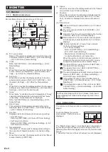
Status

Air Flow Direction

VT

Off

1

3

Off

HZ

Economy

Individual

Anti Freeze

Page  1/  4

Monitor

Next

Page

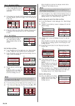
•  Air Flow Direction*: 

The air flow direction setting is displayed. The setting will 

appear only for indoor units which can set air flow direc-

tions. 

“Individual” is displayed only when this remote control-

ler is connected to the indoor unit which supports the 

appropriate function. When setting is performed, [

] is 

displayed. Refer to [3 Setting]→[3-2 Air Flow Direction 

Setting]→[3-2-3 Individual VT Hold].

•  Economy: 

ON or OFF of the economy setting is displayed.

•  Anti Freeze*: 

ON or OFF of the anti freeze setting is displayed.

< Page 2 >

• Under Maintenance

• Forced Stop

• Mode Mismatch

Previous

Page

Status

R.C. Prohibition

Special State

Page  2/  4

Monitor

Next

Page

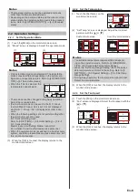
•  R.C. Prohibition: 

The functions whose operation from this unit and Wireless 

type remote controller is prohibited by the Central Control-

ler are displayed by icons. The contents of each icon are 

as follows:

:All operations

:On and Off

:On

:Mode setting

:Temperature setting

:Timer setting

:Filter sign reset

When you try to operate or set the 

prohibited function, the following 

screen is displayed and operation 

or setting is not possible. When 

the [Close] is touched, the display 

returns to the screen before opera-

tion was performed.

Setting is prohibited.

Close

< Page 2 (to 3 or 4) >

• Op. Controlled

• Set Temp. Limited

• Energy Saving Operation

• Defrost

• Oil Recovery

Status

Special State

Page  3/  4

Monitor

Previous

Page

Next

Page

• Human Sensor Setting

• Fan Control for Energy Saving

Status

Special State

Page  4/  4

Monitor

Previous

Page

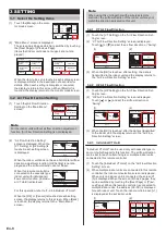
•  Special State (Page 2, 3 or 4) 

The indoor unit status is displayed. When the contents to 

be displayed exceeds 3, they are displayed on the next 

page (Page 3 or 4). The status contents are as follows: 

(Only items that indoor unit supports or operating items 

are displayed.)

Under Maintenance:

Indoor unit is inspected. Indoor unit operation is stopped 

during this time.

Forced Stop:

Indoor unit is stopped forcibly by external input.

Mode Mismatch:

A mode which cannot be operated simultaneously with a 

master indoor unit or other operating indoor unit is set in 

the same RB group of a heat recovery system or in the 

same refrigerant system of a heat pump system. In this 

case, since the mode is switched to the fan mode, reset 

to a mode that can be operated simultaneously. Refer to 

[4 OPERATION TIPS]→[4.1 Selectable Modes] for the 

modes which can be operated simultaneously.

Operation Controlled:

This content is displayed at the Slave indoor unit when 

Master indoor unit is set in the refrigerant system or RB 

Group to which this unit is connected. When a Master 

indoor unit is not set, this shows that there is already 

another indoor unit operating. Only a mode set by Master 

indoor unit or a mode that can be operated simultaneously 

with another operating indoor unit can be selected. Refer 

to [4.OPERATION TIPS] for the modes which can be oper-

ated simultaneously.

Set Temp. Limited:

Indoor unit temperature setting is limited by the Central 

controller.

Energy Saving Operation:

The energy saving is set by the Energy Manager for Sys-

tem Controller.

Defrost:

At heating operation, the outdoor unit performs Defrost 

operation. The indoor unit fan is stopped during this time.

Oil Recovery:

The outdoor unit performs oil recovery operation. The 

indoor unit fan may be stopped during this time.

Human Sensor Setting:

This function is enabled. Refer to [3 Setting]→[3-5 Special 

Setting]→[3-5-6 Human Sensor Setting].

Fan Control for Energy Saving:

This function is enabled. Refer to [3 Setting]→[3-5 Special 

Setting]→[3-5-7 Fan Control for Energy Saving].

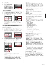
< Error Information screen >

[Error Information] is displayed only when there is an error 

history. When the [Error Information] is touched, the display 

switches to “Error Information” screen. Refer to [5-3 ERROR 

CODE] for the errors.

Status

Air Flow Direction

VT

Off

1

3

Off

HZ

Economy

Individual

Anti Freeze

Page  1/  4

Monitor

Next

Page

Error

Information

02-01

14,15, 41, 44

Error Information

Page  1/ 5

Address

Error Code

Back

Next

Page

En-5

En-6

Summary of Contents for UTY-RNRUZ2

Page 1: ...UTY RNRUZ2 PART NO 9380859697 REMOTE CONTROLLER WIRED TYPE OPERATING MANUAL WIRED REMOTE CONTROLLER Keep this manual for future reference English ...

Page 2: ...CTION SAFETY PRECAUTIONS 3 SYSTEM OUTLINE 3 1 Terminology 3 2 Password configuration 4 3 Name of parts 4 1 MONITOR 1 1 Monitor 5 1 1 1 Monitor mode screen 5 1 1 2 Status display 5 1 1 3 Vacation 7 1 1 4 Child Lock 7 1 1 5 Indoor Unit Stop 7 1 1 6 Emergency Stop 7 2 CONTROL 2 1 Operation On Off Occupied Unoccupied 7 2 2 Operation Settings 8 2 2 1 Set the Operation Mode 8 2 2 2 Set the Temperature 8...

Page 3: ...rolled Set Temp Limited Energy Saving Operation Defrost Oil Recovery Status Special State Page 3 4 Monitor Previous Page Error Information Next Page 02 01 14 15 41 44 Error Information Page 1 5 Address Error Code Back Next Page Human Sensor Setting Fan Control for Energy Saving Status Special State Page 4 4 Monitor Previous Page Error Information 3 8 3 9 Monitor Previous Page Page 2 2 Main Manu Su...

Page 4: ...y trouble or electric shock Do not insert articles into the slit parts of this unit Doing so will cause trouble heating or electric shock SYSTEM OUTLINE 1 Terminology System related terms is for VRF system a VRF system VRF Variable Refrigerant Flow is a large multi system that effectively air conditions a wide variety of spaces from large buildings to personal residences b Other system Multi or si...

Page 5: ...cklight Set ting Lightly touch the touch panel with your finger tips A commercially available stylus pen can also be used If pushed with too much force or operated with a rod pencil or ballpoint pen etc the display may be scratched or damaged Do not touch 2 or more places simultaneously Correct operation cannot be performed When cleaning the touch panel display setting child safety lock prevents e...

Page 6: ... 2 Status Display l Vacation When this is touched the schedule is disabled and the indoor unit remains unoccupied Refer to 1 1 3 Vaca tion Vacation is displayed only when a schedule is set m Status icons Indoor Unit Stop is enabled Refer to 1 1 5 Indoor Unit Stop The error occurred Refer to 5 OTHERS 5 3 Error Code Operation from this unit is prohibited by the Central Controller Refer to 1 1 2 Stat...

Page 7: ...ped during this time Forced Stop Indoor unit is stopped forcibly by external input Mode Mismatch A mode which cannot be operated simultaneously with a master indoor unit or other operating indoor unit is set in the same RB group of a heat recovery system or in the same refrigerant system of a heat pump system In this case since the mode is switched to the fan mode reset to a mode that can be opera...

Page 8: ...ndoor unit is stopped The setting cannot be performed at screens other than the monitor mode screen Custom Auto Auto Cool Heat Set Temp Mode Menu Status Vacation Fan Fri 10 00AM 76 F 80 F 74 F 84 F Room Temp Cool 68 F Heat Away Occupied 1 1 5 Indoor Unit Stop When cleaning an indoor unit or when the room is not used etc the indoor unit can be stopped When setting temporar ily stop the indoor units...

Page 9: ...8 5 R C Sensor Setting Master Indoor Unit Setting Master Indoor Unit For installer Consult authorized service personnel When the operation mode is switched in a heat recovery system operation preparations may take some time but this is not a malfunction 3 When the OK is touched the display returns to the monitor mode screen 2 2 2 Set the Temperature 1 Touch the Set Temp on the monitor mode screen ...

Page 10: ...n When Back is touched the display returns to the Main Menu screen Note When using this unit together with a wireless remote controller the air flow direction of the indoor unit may not match the direction indicated on this unit 3 2 1 VT Air Flow Direction 1 Touch the VT Setting on the Air Flow Direction Set ting screen 2 VT Air Flow Direction Setting screen is displayed Touch or and set the air f...

Page 11: ...Timer 2 Auto Off Timer screen is displayed Touch the Enable Disable on the Auto Off Timer screen 3 Enable Disable screen is displayed Touch the En able When the OK is touched the display returns to the Auto Off Timer screen 2 3 Enable Disable Disable In 30 min Operation Stop Time Time Range Setting Auto Off Timer Fri 10 00AM Cancel OK Enable Disable Cancel OK Enable Disable Set the Operation Stop ...

Page 12: ...item for details When each setting is complete or canceled the display returns to this screen When Back is touched the display returns to the Main Menu screen 3 4 1 Enable Schedule Select the schedule to be used 1 Touch the Enable Schedule on the Weekly Timer Set ting screen 2 Enable Schedule screen is displayed Select and touch Schedule 1 or Schedule 2 1 2 Back Enable Schedule None None None Sche...

Page 13: ...l Heat Occ Occ Occ Unocc When performing a different setting for other days of the week repeat 3 to 12 Copy the setting of each day of the week The contents of setting per formed at a certain day of the week can be copied to other days of the week Touch the day of the week to be copied and touch the Copy 1 2 3 4 76 F 84 F F F 68 F 76 F 72 F 80 F 08 00AM 10 00AM 12 00PM 03 00PM Back Next Page Timer...

Page 14: ...eration is off in regions where outside temperature may drop below freezing If water lines are far from the unit or within exterior walls this function may not provide enough anti freeze protection Away Setting for administrator Set the operation start temperature at Unoccupied To use this function Used must be set by R C Sensor Setting Refer to 3 8 Initial Setting 3 8 5 R C Sensor Setting Human S...

Page 15: ...reen 2 3 48 F 64 F 88 F 88 F Enable Disable Disable Set Temp Range Setting Cancel OK Lower Limit Upper Limit Heat Cool Dry Enable Disable Cancel OK Enable Disable When the OK is touched the display returns to the Set Temp Range Setting screen Set the Lower Limit and Upper Limit 4 Touch the Lower Limit Upper Limit on the Set Temp Range Setting screen 5 Setting screen is displayed Touch the Cool Dry...

Page 16: ...s to the Special Setting screen 48 F 88 F Enable Disable Enable Away Setting Cancel OK Start Temp Heat Cool 3 5 6 Human Sensor Setting for administrator 1 Touch the Human Sensor Setting on the Special Set ting screen When the Password Verification screen is displayed enter the password and touch the OK 2 Human Sensor Setting screen is displayed Touch the Auto Saving or Auto Off on the Human Sensor...

Page 17: ... Control for Energy Saving Cancel OK Enable Disable When the OK is touched the display returns to the Special Setting screen 3 6 Summer Time Daylight Saving Time Setting for administrator The time display and timer operation are 1 hour earlier than usual 1 Touch the Summer Time Setting on the Main Menu screen Monitor Previous Page Page 2 2 Main Menu Summer Time Setting Initial Setting Maintenance ...

Page 18: ...led If you repeat it press the Retry button 3 7 2 Backlight Setting 1 Touch the Backlight Setting on the Preference screen Back Preference Panel Calibration Backlight Setting Contrast Enable or disable the backlight 2 Backlight Setting screen is displayed Touch the En able Disable on the Backlight Setting screen 3 Enable Disable screen is displayed Select the Enable or Disable 2 3 Enable Disable E...

Page 19: ...h Date Setting The date and time display format are set When the power is turned off the date and time data hold time by built in battery is approximately 7 days When the power is turned off for longer than this the date and time must be reset Temp Unit Setting The temperature display unit is switched to C or F Factory settings is C R C Group Name Setting The remote controller group name can be se...

Page 20: ...te and Time Setting Date 01 01 2017 Time 12 00 AM Sun 12 00AM Cancel OK Date Format Day Month Year Time Format 12 00 11 59AM PM Summer Time Setting Disable 12 00 Sun 12 00AM Time Cancel OK hour AM min When the OK is touched the display returns to the Date and Time Setting screen Note Setting screen format corresponds to the preference of the Display format Setting 7 When the OK on the Date and Tim...

Page 21: ...e Initial Setting screen 3 8 5 R C Sensor Setting 1 Set the R C Sensor Setting on the Initial Setting screen 2 R C Sensor Setting screen is displayed Touch the Used 1 2 Back Previous Page Page 2 3 Initial Setting R C Sensor Setting Password Setting Display Item Setting Master Indoor Unit Setting Next Page R C Sensor Setting Cancel OK Used Not Used Note When set to Not Used by this setting the foll...

Page 22: ... Indoor Unit Setting Next Page Filter Sign visible invisible 2 Display Item Setting screen is displayed Touch the Filter Sign on the Display Item Setting screen 3 Filter Sign screen is displayed Touch the Visible or Invisible 2 3 Filter Sign Visible Display Item Setting Cancel OK Room Temp Invisible Filter Sign Cancel OK Visible Invisible When the OK is touched the display returns to the Display I...

Page 23: ...e 11 00 2 53 8 53 11 00 11 00 11 00 1 2015 8 1 002 01 141 2 2015 7 30 002 02 143 3 2015 7 25 002 02 143 4 2015 7 22 002 01 141 5 2015 7 22 002 01 141 6 2015 7 21 002 01 141 Page 1 2 Error History No Date Time Address Code Back Next Page Erase All AM AM AM AM AM AM 11 00 2 53 8 53 11 00 11 00 7 2015 7 1 002 01 141 8 2015 7 10 002 02 143 9 2015 7 5 002 02 143 10 2015 7 2 002 01 141 11 2015 7 2 002 0...

Page 24: ...o the following table Status Selectable Not selectable At any time Custom auto Cool Dry Fan Heat 4 1 3 RB priority connection in heat recovery system a For indoor units or RB groups by RB priority connec tion refer to the following table Status Selectable Not selectable Cooling priority is set by external input Cool Dry Custom Auto Heat Fan Heating priority is set by external input Heat Custom Aut...

Page 25: ...imum start operation 5 OTHERS 5 1 Outline Dimensions Unit in mm 4 3 4 120 4 3 4 120 13 16 20 4 All Fujitsu General products are manufactured to metric units and tolerances United States customary units are provided for reference only In cases where exact dimensions and tolerances are required always refer to metric units 5 2 Specifications Model Name UTY RNRUZ2 Input voltage DC 12 V Power consumpt...

Page 26: ......

Reviews: