background image

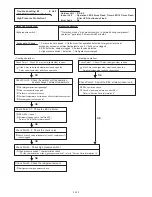
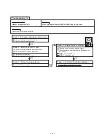
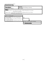
Trouble shooting 71

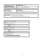
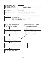
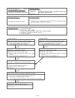
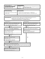
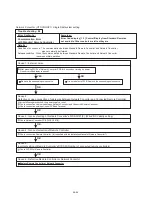
Abnormal Noise

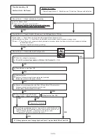
Abnormal noise is coming from Indoor Unit

(Check and correct followings)

Diagnosis method when Abnormal Noise is occurred

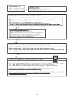
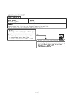
Abnormal noise is coming from Outdoor Unit

(Check and correct followings)

Attention!!

If Refrigerant Noise is occurring, Check if the Indoor and

Outdoor Thermistor is wrongly installed. Check and

correct the thermistor. 

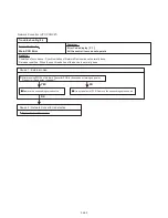
OK

Is Fan broken or deformed?

Is the screw of Fan loose?

Is there any object which obstruct the Fan rotation?

Is Fan broken or deformed?

Is the screw of Fan loose?

Is there any object which obstruct the Fan rotation?

Check if vibration noise by loose bolt or contact noise of

piping is happening.

Is Compressor locked?

>> Check Compressor (Refer to Service Parts Information)

OK

OK

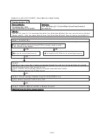
Is Main Unit installed in stable condition?

Is the installation of Air suction grille and front panel normal?

In case of Duct type : Is Static Pressure range normal? 

(Refer to Data & Technical Manual)

Is Main Unit installed in stable condition?

Is Bell Mouth installed normally?

OK

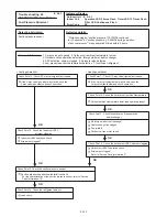
Forecast of Cause :

1. Abnormal installation (Indoor/Outdoor) 2. Fan failure(Indoor/Outdoor)

3. EEV failure (Indoor) 4. Compressor failure (Outdoor)

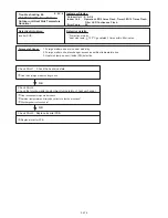
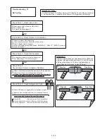
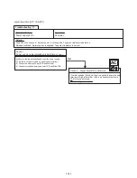
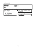
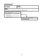
Check the refrigerant additional charging amount.

When the refrigerant is not enough, add the refrigerant.

However, the total refrigerant amount is prevented from 

more than 15.7kg.

04-79

Summary of Contents for UTP-VX30A

Page 1: ...SERVICE MANUAL ...

Page 2: ...ange of Start Stop and Operation 2 2 2 Capacity Control 02 02 2 2 1 Operation Stop Condition 2 5 SPECIAL OPERATION 02 08 02 08 02 09 2 5 2 Pre Heat Operation 2 5 1 Oil Recovery Operation 2 6 PROTECTIVE FUNCTION 02 10 02 10 2 6 1 Protective Function List 2 5 3 Defrost Operation Control 02 09 2 3 FAN CONTROL 02 04 2 4 EXPANSION VALVE CONTROL 02 07 02 04 02 06 2 3 3 Low noise mode 02 07 2 3 4 Other C...

Page 3: ...6 FUNCTION 03 14 03 14 03 15 3 6 1 Auto Restart 03 15 3 6 2 Icing Protection Control 03 15 3 6 3 Oil Recovery Operation 03 15 03 16 3 7 TIMER CONTROL 03 17 3 7 1 Wireless Remote Controller 03 17 3 7 2 Group Remote Controller 03 19 3 7 3 Wired Remote Controller 03 21 3 8 DX KIT 03 25 3 8 1 System configuration 03 25 3 8 2 3 Fundamental functions 03 26 3 8 4 Electrical expansion valve control for DX...

Page 4: ...4 03 04 03 4 2 4 Remote Controller Display 4 2 3 Error Code List for Outdoor Unit 4 2 2 Outdoor Unit Display 4 3 TROUBLE SHOOTING 04 04 04 05 4 2 5 Error Code List for Simple and Wired Remote Controller 04 07 4 2 6 Error Code List for Group Remote Controller 04 07 4 2 7 Troubleshooting No Error code rror Code List for External Switch Controller 04 08 4 2 8 Error Code List for Signal Amplifier 04 0...

Page 5: ...1 TEST RUN ...

Page 6: ... tilt is within 13 32in 10mm Excessive tilt will cause water leakage Select the size of the heat insulating material according to the ambient temperature and relative humidity of the refrigerant Use a heat insulating material having a heat conductivity of 0 043W m k or less When making flare connections always use a torque wrench and tighten the flare nut positively to the specified torque Pressur...

Page 7: ...ion check Note Perform setting by push button SW on the outdoor unit Main PCB in the power ON state after all indoor units have stopped operation When setting the address of Signal amplifier please refer to the installation manual of the signal amplifier The address setting can be set by automatically from 1 outdoor unit on the network Refer to the Page 01 06 Setting mode F3 10 Address setting for...

Page 8: ...ection points check loose terminal panel screws check 0 33mm2 shielded wire used 22AWG Connection points check loose terminal panel screws check Connection points check loose terminal panel screws check Check whether or not the heat insulation material is installed without a gap Refrigerant circuit address REF AD Indoor unit address IU AD At automatic address setting IU AD REF AD shall be 0 Remote...

Page 9: ...1 2 2 Check Items After Power ON Function setting Are the necessary functions set For the setting Refer to the page 01 16 19 Outdoor unit Main PCB push button SW setting check Note Cooling test run for each refrigerant circuit If multiple refrigerant circuits are test run at the same time refrigerant circuit address setting errors cannot be detected Judgement standard Check Check contents Procedur...

Page 10: ...he figures will be changed slightly It depends on following conditions Outdoor unit capacity Indoor and outdoor temperature Indoor unit capacity Pipe length etc Indoor unit service tool actual measurement 1 Error occured Check on the Error code on the Remote controller or Indoor unit or Outdoor unit or Service tool and check the description of the Error code Refer to the Trouble shooting in the Se...

Page 11: ...procedures below 1 FUNCTION Setting First 2 digits Last 2 digits the display when the main power is turned on When F4 to F9 are displayed continue to press the SELECT button until F3 is displayed MODE EXIT SELECT SELECT ENTER SELECT ENTER Automatic address setting for signal amplifiers Press the SELECT button until 10 is displayed Press the ENTER button for more than 3 seconds Setting is complete ...

Page 12: ... below 1 FUNCTION Setting First 2 digits Last 2 digits the display when the main power is turned on When F4 to F9 are displayed continue to press the SELECT button until F3 is displayed M SELECT SELECT ENTER 1 2 4 Automatic address setting for Indoor units It may take about 10 minutes for completing the processing End First 2 digits Last 2 digits Press the SELECT button until 11 is displayed Press...

Page 13: ...door unit and outdoor unit Press the ENTER button for more than 3 seconds This will be displayed when the Indoor unit connection check starts MODE EXIT SELECT ENTER ENTER ENTER 1 2 1 The number of connected indoor units 2 Volume ratio of the indoor units connection Ex When 8 units are connected Ex When the ratio is 120 Please refer to the following Error code for details Note Error code 22 1 Conne...

Page 14: ...ction select condition Function mode SWITCH POSITION SW107 SW108 SW109 MODE EXIT SELECT ENTER LED101 GREEN POWER MODE LED105 LED104 LED102 RED ERROR Push button switch 7 Segment LED Lamp Outdoor unit printed circuit board TEST RUN SETTING Monitoring mode Setting mode Error history mode For a detailed description of push button operation refer to the D T manual Chapter 6 SYSTEM DESIGN LED105 LED104...

Page 15: ...al and perform operation check Check that there are no abnormal sounds or vibration sounds during test run operation Perform the test operation for 60 minutes 1 Standard wired remote controller UTY LNH UTY RNK Stop the indoor and outdoor units Push the remote controller button and button simultaneously for more than three seconds The air conditioner will start to conduct a test run and will displa...

Page 16: ...onitor Group 1 2 Monitor All UTY DCG On Coll 25 0 05 31 03 59 05 31 03 59 05 31 03 59 Test Operation 05 31 03 59 RCG_05 Test run operating procedure 4 Central remote controller LED lamp Arrow MENU OK CANCEL Function buttons F1 5 Monitor screen 9 units display Password verification 1 Press Button 2 Press the Setup Menu F2 button 5 Press the Select All F2 button or Identify Unit F3 button 6 Press th...

Page 17: ...wn List Heat Auto Cool 26 0 C 24 0C Auto 22 0 C Auto 24 0 C 21 5 C Heat 21 5 C 21 5 C Cool Off Off Off All 21 0 C Heat All LangeGroup LangeGroup Top Up Down List OfficeA PC Room Room 101 Restrant Entrance Meeting 1 Off Off Off Mixed Heat Auto Cool 24 0 C 26 0 C Low Auto 21 5 C High Office B Mixed Mixed Mixed Mixed Name Expand Status Mode Set Temp Fan R C Prohibit On On On Status On Status On 10 11...

Page 18: ...ion of the objective devices by pressing Off of Operation and then pressing OK on the setting screen 3 4 5 Cancel Off On OK Transferring data Please wait On On Reset Cancel Stand by Defrost Stand by Oil Recovery Test Operation Start Air Flow Direction Economy AntiFreeze Filter Sign Operation Test Up Down Swing Swing Left Right Off Off Special State Status On 1 2 3 4 5 1 2 3 4 Setting Optional Canc...

Page 19: ... Page and press Test Run the Test run screen is displayed 4 Press OK The test run continues for 60 minutes To interrupt test run before it is complet return to the Monitor Mode Screen and press ON OFF Monitor Mode Screen Main Menu Screen Maintenance Screen UTY RNR Test Run Screen 01 14 6 2 Wire type wired remote controller ...

Page 20: ... refrigerant circuit will start to conduct a test run in accordance with the operation mode set by push switch of outdoor unit see 1 2 3 4 After 60 minutes passes the test run stops 5 Test running initialization is shown below Fan speed Hi Hi Room Temperature Indication 18 30 Hi Hi 18 30 Vertical Air Direction Panel Swing Operating Mode Cooling Heating Cooling Heating OFF OFF Position 1 Position 4...

Page 21: ...r Accumulated time is displayed in the heating operation of the 23 INV compressor 10 hour Refrigerant cycle data 1 Refrigerant cycle data 2 30 Information on Thermistor 1 INV compressor discharge temperature sensor 32 33 34 The value of the Thermistor 1 is displayed 31 The value of the Thermistor 3 is displayed The value of the Thermistor 4 is displayed 35 C or F C or F C or F The value of the The...

Page 22: ...of function 2 01 17 40 41 42 50 51 60 61 64 Capacity priority setting Low noise mode setting Low noise level setting Forbidden Factory defalut Level 1 Off quiet priority On capacity priority Off Normal On Low noise mode operation is always done 00 01 00 00 00 01 Low noise setting 1 70 71 72 3 73 7 Electricity meter No setting 1 Set the ones digit and tens digit of the No of the electricity meter c...

Page 23: ... Maximum memorized indoor unit number is reset 91 Forced Central control function release When the centralized control device failure and the centralized control setting cannot be released this function is used All the limitations set with the centralized control device are released E14 5 Indoor unit number shortage error is cleared code is reset This is a function that uses to clear abnormal disp...

Page 24: ...8GALH ARXD24GALH SP mode 00 to 05 0 to 50 Pa ARXA24GBLH SP mode 00 to 14 40Pa ARXA30GBLH 50Pa ARXA36GBLH SP mode 00 to 12 ARXA45GBLH SP mode 00 to 11 60Pa ARXC36GBTH SP mode 02 to 16 100Pa ARXC72GBTH SP mode 04 to 27 150Pa ARXC90GBTH SP mode 05 to 24 ARXC96GATH SP mode 05 to 29 ARXN18GATH SP mode 05 to 10 50Pa ARXN24GATH SP mode 05 to 15 ARXN30GATH SP mode 05 to 25 ARXN34GATH ARXN36GATH 60Pa ARXN4...

Page 25: ...ange the target for reporting errors Errors can either be reported in all locations or only on the wired remote 01 Display only on central remote control Fan setting when cooling thermostat OFF 49 00 Follow the setting on the remote controller When set 00 Indoor unit is continued operation based upon Central remote controller or individual controller set Once indoor unit received signal from Exter...

Page 26: ... SP 1 Auto restart 40 00 Enable Enable or disable automatic system restart after a power outage 01 Disable Cool Air Prevention 43 00 Prohibited Setting change prohibited 01 Follow the setting on the remote controller External control 46 00 Start Stop Allow an external controller to start or stop the system or to perform an emergency stop or to perform a forced stop If an emergency stop is performe...

Page 27: ...2 OUTDOOR UNIT OPERATION CONTROL ...

Page 28: ...ve coil AC220 240V 50 60Hz 6 5 W Crank case heater For Inverter Compressor AC240V 35W Base heater Field supply AC220 240V 35W LON WORKS Inverter communication External input 1 CN131 Low noise mode operation External input 2 CN132 Cooling Heating priority External input 3 CN133 Outdoor unit operation peak control External input 4 CN134 Emergency stop operation Dry contact input Single LED 101 Singl...

Page 29: ...tion Icing protection Failure Refer to chapter 4 TROUBLE SHOOTING Under expansion valve initialization At protective operation Emergency stop Defrost operation 02 02 2 2 COMPRESSOR OPERATION 2 2 2 Capacity Control 1 Capacity of compressor operation By the operation of DC inverter rotary compressor the amount of required refrigerant circulation acceding to cooling and heating load can be supplied f...

Page 30: ...or operation pipe length and capacity shift switch settings Cooling Heating 02 03 2 2 3 Speed Range of Start Stop And Operation On stop mode 0 rps On operating mode 15 120 rps 1 Heating starting process The compressr starting process in cool mode does not have the limitated hold controlling For Heating operation only the upper limit speed at starting is made 40rps and is raised in 10rps increments...

Page 31: ... 6 54 High pressure saturation temperature Outdoor temperature Upper limit of target high pressure saturation temp Low limit of target high pressure saturation temp Target high pressure saturation temp Thereafter the high pressure is monitoring at a set time interval and the fan speed is changed by the following conditions The fan is controlled to keep high puressure saturation temperature within ...

Page 32: ...itial speed of the first boot outdoor unit is detected by outdoor air temperature sensor value TAOUT Fan step 11 10 9 8 7 6 5 4 3 2 1 0 680 680 660 660 590 510 520 400 440 330 380 300 300 300 450 0 300 0 0 0 0 0 Fan speed rpm 780 740 660 660 590 510 520 400 440 330 380 300 300 300 450 0 300 0 0 0 0 0 790 710 700 620 590 510 520 400 440 330 380 300 300 300 450 0 Intermittent 1 0 0 0 0 0 Step Upper ...

Page 33: ... the outdoor unit operates in the low noise mode as follows LOW NOISE MODE The operating sound lowers from about 3 to 5 dB more than the rated value Capacity does not become low even when switched to low noise mode The operating noise is reduced by limiting the rotational speed of the compressor and fan motor 2 3 3 Low noise mode 400 48 590 9 510 63 700 10 620 80 520 8 400 55 590 9 510 65 700 10 6...

Page 34: ...reaches closer to the target discharge temperature that is calculated from high and low pressure Cooling mode Heating mode 3000 pulses basically Initialization conditions Control range operation stop 3000 Plulses 55 500 pulses 0 pulses 40 pulses 2 4 EXPANSION VALVE CONTROL Cooling Heating Operation mode 160 3000 pulses Cooling Heating When power turned on When operation stopped ...

Page 35: ...elapsed since the start Operation COMPRESSOR The rotation speed varies depending on the operation state EEV Opening Indoor Outdoor unit Controlled pulse as normal operation mode FAN speed Indoor Outdoor unit Controlled fan speed as normal operation mode 3 Oil Recovery in Heating operation 1 Oil Recovery in Cooling operation Start condition Compressor accumulated operation time since the last heati...

Page 36: ...exchange liquid temperature end judgment temperature or when 15 minutes have elapsed from the start Defrosting end judgment temperature 0 39 x outdoor temperature 12 7 However 5 to 12 C range If the calculated result is lower than 27 6 the judgment temperature is defined as 27 6 If the calculated result is higher than 6 the judgment temperature is defined as 6 2 5 2 Pre heat Operation This pre hea...

Page 37: ... unit gradually opened upper limit 200pls Discharge Temp Protection Stop Discharge Temp Thermistor Pattern starting condition Discharge temperature fixed value 120 C Pattern reset condition 3 minutes have elapsed and discharge temperature 85 C Compressor stopped Pattern starting condition Pattern generated 2 times within 40 minutes Pattern reset condition Error reset push button SW executed after ...

Page 38: ...g condition Low pressure 0 16MPa Compressor capacity lowered every 180 secs Low Pressure Protection Stop Low Pressure Sensor Pattern starting condition Low pressure 0 05MPa or low pressure 0 10MPa continues for 10 mins Pattern reset condition 3 minutes have elapsed and low pressure 0 17MPa Pattern starting condition Pattern generated 5 times within 180 minutes Pattern reset condition Error reset p...

Page 39: ...ctioncircuit in the inverter PCBoad detects an abnormal current duringthe operation If it repeated 5 times the compressor becomes permanentstop Compressor is stopped when the over current protection circuit in the inverter PC Board detects an abnormal current at the time of start up Compressor becomes permanent stop if it repeated over the number of set time Reset condition Error reset push button...

Page 40: ...3 INDOOR UNIT OPERATION ...

Page 41: ...ing operation fan speed is decided by the difference between the room temperature and the set temperature 1 The indoor fan starts operation 5 seconds after the electric expansion valve opens However when the indoor unit just starts its operation or the operation mode is changed from other to DRY and the refrigerant circulation is not stopped the fan will rotate immediately without a delay time of ...

Page 42: ...dry from the connected indoor units There are 3 priority modes of Neutral Cooling Priority and Heating Priority The operation modes restricted by each of these modes are as follows Priority mode Neutral Cooling priority Heating priority Restricted operation mode No restrictions Heating Cooling dry Neutral Cooling priority Heating priority Cooling priority Heating priority 1 Priority mode decision ...

Page 43: ...r unit regardless of the current priority mode The priority mode is fixed at either cooling or heating even if the master indoor unit stops Cooling heating switching can be performed by the master indoor unit only 4 Opposite operation mode When the operation mode commanded from an indoor unit remote controller and the operation mode allowed by the system cooling and dry operation for cooling only ...

Page 44: ...revention control Each operation mode is controlled as below 1 Stop mode Outdoor air unit fan motor OFF Electric expansion valve Drain pump Stop pulse Turns ON OFF by the drain pump control function Solenoid valve Closed Operates according to the HIGH MODE setting Heat Pulse controlled by the temperature difference Each operation mode is controlled as below Fan Operates according to the HIGH MODE ...

Page 45: ... The purpose of the priority mode is to restrict operation commands heating cooling from the connected outdoor air units There are 3 priority modes of Neutral Cooling Priority and Heating Priority The operation modes restricted by each of these modes are as follows Priority mode Neutral Cooling priority Heating priority Restricted operation mode No restrictions Heating Cooling Neutral Cooling prio...

Page 46: ...nit by outdoor unit DIP SW 2 Set the master indoor unit by wired remote controller 3 Judge cooling heating by the difference between the master indoor unit s setting temperature and the room temperature Thermostat remains in OFF state for 6 minutes or longer System stops or operation command other than auto changeover operation NO NO Thermostat remains in OFF state for 6 minutes or longer System s...

Page 47: ...ster outdoor air unit by wired remote controller 3 Judge cooling heating by the difference between the master outdoor air unit s setting temperature and the suction airflow temperature Thermostat remains in OFF state for 6 minutes or longer System stops or operation command other than auto changeover operation NO NO Thermostat remains in OFF state for 6 minutes or longer System stops or operation ...

Page 48: ... of refrigrant flow The thres hold temperature of stop of refrigrant flow Ts 0 5 C Ts 0 5 C 3 2 4 HEAT Position 1 When using the heating mode set the temperature to a value higher than the current room temperature otherwise the indoor unit will not start the heating operation 3 An example for HEATING TEMPERATURE CONTROL time chart Manual setting During defrosting the OPERATION indicator lamp flash...

Page 49: ...her than the discharge airflow temperature otherwise the outdoor air unit will not start the heating operation 2 An example for HEATING TEMPERATURE CONTROL time chart Manual setting During defrosting the OPERATION indicator lamp flashes 6 sec ON and 2 sec OFF and repeat The heating operation will be temporarily interrupted Excess capacity area Compressor ON 6 minutes Compressor ON 6 minutes Compre...

Page 50: ...tempting to move them manually could result in improper operation in this case stop operation and restart The louvers should begin to operate properly again When used in a room with infants children elderly or sick persons the air direction and room temperature should be considered carefully when making settings COMPACT WALL MOUNTED TYPE COMPACT FLOOR TYPE CASSETTE TYPE 1 3 4 2 1 2 3 4 Press the V...

Page 51: ...TYPE COMPACT WALL MOUNTED TYPE and COMPACT FLOOR TYPE 1 3 4 5 2 03 11 1 2 3 4 5 Press the VERTICAL SWING button for more than two seconds The remote controller s Vertical Swing Display will light up In this mode the UP DOWN air direction flaps will swing automat ically to direct the air flow both up and down Example When set to vertical swing 1 3 4 5 2 Press the HORIZONTAL AIRFLOW DIRECTION button...

Page 52: ...NTAL SWING button for more than two seconds once and again The remote controller s Horizontal Swing Display will go out Airflow direction will return to the setting before swing was begun Example When set to horizontal swing Range of swing 03 12 The SWING operation may stop temporarily when the air conditioner s fan is not operating or when operating at very low speeds The swing operation is not a...

Page 53: ... the drain pump will turn off in 1 hour after the end of indoor heat exchanger frost prevention operation 4 When the water level in the drain pan rises up and then the float switch functions Microcomputer stops the refrigerant circulation and indoor fan motor operation Drain pump operates continuously for 3 minutes after the float switch is turned off Almost condensing water may be drained 5 When ...

Page 54: ...operates continuously for 3 minutes after the refrigerant circulation stopped 3 When the refrigent circulation is stopped by a start of indoor heat exchanger frost prevention operation the drain pump will turn off in 1 hour after the end of indoor heat exchanger frost prevention operation 4 When the water level in the drain pan rises up and then the float switch functions Microcomputer stops the r...

Page 55: ... EEV Control pulse During the above operation a refrigerant noise may be from the indoor unit The icing of the indoor heat exchanger is prevented during the cooling and dry mode operation 1 Starting Condition Compressor is operation more than 3 minutes When Heat exchanger inlet temperature TA continues 4 minutes or more Compressor is operation more than 3 minutes When Heat exchanger outlet tempera...

Page 56: ...ration mode management is made Management by indoor unit and outdoor air unit is master indoor unit 5 C 18 C Suction airflow temperature rises Suction airflow temperature drops 20 C 10 C 5 C 7 C Forced thermostat off and Fan off Cooling operation Fan operation 18 C Suction airflow temperature rises Suction airflow temperature drops 20 C 10 C 5 C Forced thermostat off and Fan off Heating operation ...

Page 57: ...e used when this controller is used together with the remote controller Wired type A beeping sound is made when a signal is received To set the ON OFF timer 1 2 Adjust the OFF or ON time About 5 seconds later the entire display will reappear Press the TIMER MODE button to select OFF TIMER or ON TIMER CANCEL OFF TIMER ON TIMER PROGRAM TIMER OFF ON OFF ON Press the START STOP button to start the air...

Page 58: ...ng operation dry operation Heating operation When the sleep timer is set the set temperature automatically rises 1 C every hour The set temperature can rise up to a maximum of 2 C Timer setting 60min 1 C 2 C When the sleep timer is set the set temperature sutomatically drops 1 C every 30 minutes The set temperature can drop to a maximum of 4 C 1 C 2 C 3 C 4 C 30min 60min 90min Timer setting ...

Page 59: ...its Press the Select button to select the indoor unit Press the PROGRAM CLOCK AD JUST button Do not press this button for two sec onds or more otherwise you will en ter the time setting mode Press the Select button to select the indoor unit If all indoor units are selected the times for all of the registered indoor unit timers are set at once ı ˇ ı Day of the week setting S M T W T F S ALL All ind...

Page 60: ... complete the weekly timer setting flashes for two seconds ı ˇ ı Setting the timer for the other indoor units Before setting the timer for other indoor units press the ENTER button to confirm the settings The display switches to the next timer Repeat steps to to set the timer for other indoor units 2 6 1 If the Timer Mode DELETE button is pressed during steps to the operat ing time for the selecte...

Page 61: ...m when the button is pressed 2 Press the DELETE button to cancel the timer mode The timer mode can also be canceled by changing the timer mode using the timer mode button 1 NON STOP OFF TIMER ON TIMER WEEKLY TIMER No display Press the set time buttons to set the time After the time is set the timer will start automatically The amount of time until the OFF timer operates that is displayed on the ti...

Page 62: ... necessary set the second weekly timer settings in the same way When the operating time is set the mark appears 6 Press the TIMER SET button for 2 seconds or more to complete the weekly timer settings To delete the operating time If the TIMER DELETE button is pressed during steps or the operating time for the selected day will be deleted If all the days are selected the operating times for all of ...

Page 63: ...he DAY OFF setting is cancelled automatically after the set day has passed Flashing mark indicates the DAY OFF ON OFF ON OFF DAY OFF WEEKLY WEEKLY WEEKLY WEEKLY ON OFF ON OFF DAY OFF To start cancel the WEEKLY timer operation To set the DAY OFF for a holiday 3 6 9 12 15 18 21 The operating time for the current day is displayed ex Operating time 7 00 18 00 Indpnd OFF time 21 00 The independent time...

Page 64: ...eratures as low as 10 12 and 14 C cannot be set depending on the model SET BACK SU MO TU WE TH FR SA 3 6 9 12 15 18 21 SU MO TU WE TH FR SA 3 6 9 12 15 18 21 ex When setting all days together Temperature setting Press the set temperature buttons to set the temperature The temperature setting range is the same as the range for the operation mode ex Operating time 15 00 22 00 5 Repeat steps and Pres...

Page 65: ...ected Interface External input External output Contents Fan ON OFF Thermostat ON OFF Interface External input External output Contents Operation ON OFF Operation mode Cool Heat Set temperature or capacity request Analog input Error Operation ON OFF Error Special operation defrost Remarks Typical indoor unit is required for mode changing Temperature setting When thermo control is performed by DX ki...

Page 66: ...input Capacity input Selection Intake temperature Room temperature Cooling 18 to 30 Heating 10 to 30 Cooling Intake temperature Setting temperature 0 5 Heating Intake temperature Setting temperature 0 5 0 5 to 100 Controlled by external controller and EEV closed by making the capacity input 0 in cooling mode EEV slightly opened when the Compressor operating in heating mode Controlled by external c...

Page 67: ...Target controlling temperature Air intake temperature or Air discharge temperature Duration of cold air prevention 2 After the start of heating operation the fan of indoor unit will not rotate until the heater exchange is warmed up to blow out warm air TR Target controlling temperature Air intake temperature or Air discharge temperature 0 5 C Air intake ctrl C Air discharge ctrl 0 5 C Air intake c...

Page 68: ...vention operation the drain pump will turn off in 1 hour after the end of indoor heat exchanger frost prevention operation 4 When the water level in the drain pan rises up and then the float switch functions Microcomputer stops the refrigerant circulation and indoor fan motor operation Drain pump operates continuously for 3 minutes after the float switch is turned off Almost condensing water may b...

Page 69: ... operation Stop DX KIT EEV Control pulse During the above operation a refrigerant noise might hear from the EEV Kit The icing of the indoor heat exchanger is prevented during the cooling and dry mode operation 1 Starting Condition Compressor is operation more than 3 minutes When Heat exchanger inlet temperature TA continues 4 minutes or more Compressor is operation more than 3 minutes When Heat ex...

Page 70: ...4 TROUBLE SHOOTING ...

Page 71: ...Timer LED Timer Continuous lighting Operation LED Operation Flashing Pattern Indication Lamp Indication type 04 01 Opposite Operation Mode 4 1 NORMAL OPERATION 4 TROUBLESHOOTING 4 1 1 Indoor Unit Display Filter Filter LED Continuous lighting ON OFF ON OFF 1 sec 1 sec 6 sec 2 sec ON OFF ON OFF Operation LED Timer LED Filter LED Maintenance Mode 1 sec 1 sec 1 sec 1 sec 3 sec 1 sec ON OFF 1 sec 1 sec...

Page 72: ...ing Description POWER LED101 ERROR LED102 ON ON OFF OFF P ROTECT 4 ON OFF 1 sec 1 sec Peak Cut Mode Starting condition Discharge temp fixed value 120 C Release condition 3 minutes have elapsed and discharge temperature 85 C Starting condition Compressor temp fixed value 130 C Release condition 3 minutes have elapsed and discharge temperature 90 C Starting condition Low pressure 0 05MPa or low pres...

Page 73: ...ous flash 4 times flash 1 times flash 1 2 3 Trouble shooting Filter LED Timer LED Operation LED Please refer the flashing pattern as follows 04 03 4 2 ABNORMAL OPERATION 4 2 1 Indoor Unit Display Indoor Unit Power Supply Error For Fan Motor 1 2 Outdoor Air Unit Temperature Sensor Error Indoor Unit Fan Motor 2 Error LED Display when Option receiver unit installed Error Indication Flashing Pattern 0...

Page 74: ...play is changed by SELECT short press ENTER short press ENTER short press ENTER short press ENTER long press Short press less than 3 seconds Long press more than 3 seconds Annunciation Type of errors Address SELECT short press display change SELECT short press display change If some error is newly occured or resolved during transition it is reflected after going back to Annunciation Only in the ca...

Page 75: ...or Temp Sensor Error TH10 Discharge Temp Sensor Error TH1 40 Outdoor unit FAN Motor 1 Under voltage Outdoor unit Fan Motor 1 Lock Error Start up Error Compressor Motor Loss of Synchronization Trip Detection Inverter Compressor Start Up Error Outdoor unit Fan Motor 1 Temperature Abnormal 55 54 53 52 51 Error Code 8 6 3 8 6 4 9 3 1 9 4 1 9 5 5 9 7 1 9 8 5 9 A 1 9 A 2 A 1 1 A 3 1 Discharge Temperatur...

Page 76: ...del code Outdoor unit Indoor unit Group remote controller Convertor 1 1 If an error occurs the following display will be shown will appear in the set room temperature display If is displayed immediately contact authorized service personnel 4 2 4 Remote Controller Display 1 Touch the Status on the Monitor mode screen 2 Touch the Error Information on the Status screen 2 digit numbers are correspondi...

Page 77: ...door Unit Error 7 8 13 14 15 16 22 23 21 26 30 66 30 34 36 13 21 14 15 16 22 23 26 28 37 38 40 47 48 49 53 55 54 56 59 61 62 63 64 65 A C Outdoor unit Heat Sink temp Abnormal 66 90 Group Remote controller Hardware Error 4 C 88 r o r r E e r a w t f o S A C C 1 Main PCB Error 9 8 Outdoor Unit Fan Motor 2 Error 9 A Coil Expansion Valve Error 60 7 1 7 2 7 3 7 4 7 5 7 7 Heat Sink Temperature Sensor Er...

Page 78: ... Main PCB Error 83 84 88 2 6 Refrigerant circuit address setting error 89 85 86 LED D14 Flashing or Lighting Error indication of converter 1 6 Peripheral device Communication abnormal 87 OFF LED D9 Flashing or Lighting 4 2 7 Trouble shooting No Error code Trouble shooting Error condition Indoor Unit No Power Outdoor unit No Power No operation Power is ON No Cooling Abnormal Noise Indoor Unit No Po...

Page 79: ...ntroller PCB Check terminal voltage of controller PCB Connector CNC01 Power supply for Remote If DC12V Remote Control failure Controller PCB is OK Replace Remote controller If DC0V Controller PCB failure Remote is OK Replace Controller PCB In case of re installation is done due to removed connector or incorrect wiring turn on the power again Check Point 1 Check the connection of terminal After tur...

Page 80: ...mal 2 Mis setting 3 Wired Remote Control failure 4 Controller PCB failure Check Point 1 Check the connection of terminal After turning off the power check correct the followings Indoor Unit Check the connection of terminal between remote control and Indoor unit or between Indoor units and check if there is a disconnection or short of the cable Check Point 2 Check Remote and Controller PCB Check te...

Page 81: ... the number of connecting Indoor unit and Remote controller in one RCgroup exceeds more than 32 units Check Point 2 Check Indoor unit controller PCB The number of connecting indoor unit and Remote controller in one RCgroup were less than 32 units Forecast of Cause 1 Wrong wiring of RCgroup 2 Indoor unit controller PCB failure Check Point 1 Wire installation Wrong RCgroup setting Wrong wire connect...

Page 82: ...r more from all indoor units that once received communication Check Point 4 Check the Terminal resistor setting Terminal resistor setting check Check Point 6 Replace Main PCB outdoor unit indoor unit Check Point 5 Check the communication PCB outdoor unit indoor unit Change Main PCB and set up the original address Detective details 1 Noise momentary open voltage drop 2 Indoor unit power off 3 Commu...

Page 83: ...B Replace Communication PCB of the Indoor units that have the error OK Forecast of Cause 1 Outside cause 2 Connection failure 3 Communication PCB failure 4 Controller PCB failure Check Point 1 Check if any outside cause such as voltage drop or noise Instant voltage drop Check if there is any electric equipment with a large load within the same circuit Momentary power failure Check contact failure ...

Page 84: ...o related cables near the power line Check Point 2 Check the indoor unit power supply Main power ON check Power cable connection and open check Check Point 3 Check the communication line connection Check Point 4 Check the Terminal resistor setting Terminal resistor setting check Check Point 6 Replace Main PCB and Communication PCB indoor unit outdoor unit Change Main PCB and Communication PCB and ...

Page 85: ...change replace Controller PCB and set up the original address Check Point 1 2 Check outside cause such as noise Check the complete insulation of the grounding Check if there is any equipment that causes harmonic wave near the power cable Neon light bulb or any electronic equipment which causes harmonic wave Check Point 1 1 Reset the power Check Point 2 Check Connection YES NO Does LED error indica...

Page 86: ...of signal amplifier Refer to the Installation manual Check Point 3 Check Communication PCB Replace Communication PCB of the Indoor units that have the error OK Forecast of Cause 1 Outside cause 2 Connection failure 3 Communication PCB failure 4 Controller PCB failure Check Point 1 Check if any outside cause such as voltage drop or noise Instant voltage drop Check if there is any electric equipment...

Page 87: ...n the duplicated address number exists in one RCgroup Check Point 3 Check Indoor unit controller PCB Forecast of Cause 1 Wrong wiring of RCgroup 2 Wrong remote address setting 3 Indoor unit controller PCB failure 4 Remote controller failure Check Point 1 Wire installation Wrong wire connection in RCgroup Please refer to the installation manual Change controller PCB and check the Error after settin...

Page 88: ...RC group Check Point 3 Check Indoor unit controller PCB Forecast of Cause 1 Wrong wiring of RCgroup 2 Wrong remote address setting 3 Indoor unit controller PCB failure 4 Remote controller failure Check Point 1 Wire installation Wrong wire connection in RCgroup Please refer to the installation manual Check if controller PCB damage Change controller PCB and check the Error after setting remote contr...

Page 89: ...rs Wired remote controller 2 Wire Indoor unit Controller PCB circuit Detective details When the number of connecting indoor units are out of specified rule Check Point 2 Check Indoor unit controller PCB Forecast of Cause 1 Wrong wiring Number of I U RC in RCgroup 2 Indoor unit controller PCB defective Check Point 1 Wire installation Wrong number of connceting indoor unit Change controller PCB and ...

Page 90: ...tive details When the number of connecting remote controller are out of specified rule Check Point 2 Check Indoor unit controller PCB Forecast of Cause 1 Wrong wiring Wrong number of connecting RC in RCgroup 2 Remote controller PCB defective Check Point 1 Wire installation Wrong number of connceting remote controller Change controller PCB and check the Error after setting remote controller address...

Page 91: ...lation defect is found correct it by referring to Installation Manual OK Check power supply voltage AC198 264V between Indoor unit terminal 1 and 2 Check connection of Connector any lose connector or incorrect wiring Check any shortage or corrosion on PCB OK Check Point 1 1 Reset Power Supply Does abnormal LED indication show again Check Point 1 2 Check outside cause Voltage drop or noise etc Inst...

Page 92: ...er failure Check if there is a defective contact or leak current in the power supply circuit Noise Check if there is any equipment causing harmonic wave near electric line Neon bulb or electric equipment that may cause harmonic wave Check the complete insulation of grounding Check Point 3 Replace Controller PCB Change Controller PCB and set up the original address Check Point 1 1 Reset Power Suppl...

Page 93: ...p or noise etc Instant drop Check if there is a large load electric apparatus in the same circuit Momentary power failure Check if there is a defective contact or leak current in the power supply circuit Noise Check if there is any equipment causing harmonic wave near electric line Neon bulb or electric equipment that may cause harmonic wave Check the complete insulation of grounding Check Point 3...

Page 94: ...Voltage drop or noise etc Instant drop Check if there is a large load electric apparatus in the same circuit Momentary power failure Check if there is a defective contact or leak current in the power supply circuit Noise Check if there is any equipment causing harmonic wave near electric line Neon bulb or electric equipment that may cause harmonic wave Check the complete insulation of grounding Ch...

Page 95: ...voltage drop or noise Instant voltage drop Check if there is any electric equipment with a large load within the same circuit Momentary power failure Check contact failure or leak current in power supply circuit Check if there is any equipment that causes harmonic wave near the power cable Neon light bulb or any electronic equipment which causes harmonic wave And check the complete insulation of g...

Page 96: ...voltage drop or noise Instant voltage drop Check if there is any electric equipment with a large load within the same circuit Momentary power failure Check contact failure or leak current in power supply circuit Check if there is any equipment that causes harmonic wave near the power cable Neon light bulb or any electronic equipment which causes harmonic wave And check the complete insulation of g...

Page 97: ...er Trans is failure Replace Power Trans OK Forecast of Cause l a m r o n b A n o i t c e n n o C l a n i m r e T 1 l a m r o n b A y l p p u S r e w o P 2 3 Power Trans 4 Power Supply PCB 5 Controller PCB 6 Cable Connection failure Check the connection of terminal between Power Trans and Power Supply PCB CN113 and Check if there is a disconnection or short of the cable If AC24V To the Check Point ...

Page 98: ...ler PCB Forecast of Cause 1 Terminal connection abnormal 2 Wired remote controller failure 3 Indoor unit controller PCB defective Check Point 1 Check the connection of terminal Indoor unit Check the connection of terminal between remote control and indoor unit or between Indoor units and check if there is a disconnection or short of the cable Check terminal voltage of controller PCB connector CNC0...

Page 99: ...rted replace it and reset the power Check Point 1 Check connection of Connector Check if connector is loose or removed Check erroneous connection Check if sensor cable is open Reset Power when reinstalling due to removed connector or incorrect wiring 6 5 35 8 0 30 10 0 12 5 15 8 20 2 25 9 33 6 3 03 2 77 2 50 2 22 1 94 1 66 1 39 1 15 3 68 3 48 3 27 25 20 15 10 5 0 Temperature C 3 6 4 3 5 3 50 45 40...

Page 100: ...r Check if connector is loose or removed Check erroneous connection Check if thermistor cable is open Reset Power when reinstalling due to removed connector or incorrect wiring OK OK Check Point 2 Remove connector and check sensor resistance value Check Point 3 Check voltage of Controller PCB DC5 0V Corresponding connector Heat Ex Inlet temp Sensor Black Wires Model Type 32 4 35 40 0 30 49 8 62 5 ...

Page 101: ... Power when reinstalling due to removed connector or incorrect wiring OK Check Point 3 Check voltage of Controller PCB DC5 0V Corresponding connector Heat Ex Outlet temp Sensor Gray Wires DC Sensor Characteristics Rough value If Thermistor is either open or shorted replace it and reset the power OK Check Point 2 Remove connector and check sensor resistance value 32 4 35 40 0 30 49 8 62 5 79 1 100 ...

Page 102: ...nector defective connection 2 Thermistor defective 3 Controller PCB defective Check Point 1 Check connection of Connector Check if connector is loose or removed Check erroneous connection Check if thermistor cable is open Reset Power when reinstalling due to removed connector or incorrect wiring OK Check Point 2 Remove connector and check sensor resistance value Check Point 3 Check voltage CN9 of ...

Page 103: ...Connector defective connection 2 thermistor defective 3 Controller PCB defective Check Point 1 Check connection of Connector Check if connector is loose or removed Check erroneous connection Check if thermistor cable is open Reset Power when reinstalling due to removed connector or incorrect wiring OK Check Point 2 Remove connector and check sensor resistance value Check Point 3 Check voltage CN9 ...

Page 104: ...fer to the PARTS INFORMATION 13 14 If Fan motor is abnormal replace it Check Point 1 Check rotation of Fan Rotate the fan by hand when operation is off Check if fan is caught dropped off or locked motor If Fan or Bearing is abnormal replace it Check Point 3 Check ambient temp around motor Check excessively high temperature around the motor If there is any surrounding equipment that causes heat Upo...

Page 105: ...CB DC 12V output abnormal 5 Noise momentary open voltage drop Trouble shooting 27 E52 1 E52 2 Indicate or Display Detective Actuators Detective details INDOOR UNIT Error Method Forecast of Cause Check if the DC 12 is on between the pin No 1 of CN10 CN11 and GND Pin No 6 of CNB01 Pin No 7 of CNB01 Disconnect the wire of EEV1 2 when you check the output of EEV1 2 OK Check if the circuit of EEV coil ...

Page 106: ...ecast of Cause 1 Drain Installation 2 Drain pipe line blockage 3 Float switch defective 4 Shorted connector wire 5 Controller PCB defective Drain pump defective Check Point 5 Check controller PCB defective Drain pump defective Check Point 1 Check Drain pipe installation OK Check Drain pipe installation Refer to the installaion manual The Height limit for Drain pump The angle of drain pipe The angl...

Page 107: ... motor is abnormal replace it Check Point 1 Check rotation of Fan Rotate the fan by hand when operation is off Check if fan is caught dropped off or locked motor If Fan or Bearing is abnormal replace it Check Point 3 Check ambient temp around motor Check excessively high temperature around the motor If there is any surrounding equipment that causes heat Upon the temperature coming down restart ope...

Page 108: ...ginal address 4 3 2 Trouble Shooring With Error Code OUTDOOR UNIT 1 Wrong DIP SW setting 2 Power supply defective 3 Main PCB defective Indoor Unit No Display Outdoor Unit Flashing 0 5 sec ON and OFF Error Code No Display Trouble shooting 30 Indicate or Display Detective Actuators Detective details OUTDOOR UNIT Error Method Forecast of Cause When the DIP SW setting was wrong after turned on the pow...

Page 109: ...installation manual shows Check Point 4 Check noise momentary open voltage drop Check if power supply temporarily stops by outages or if strong noise is generated from surrounding environment during auto address Check Point 3 Check the communication line connection Indoor Unit No Display Outdoor Unit E 28 1 Error Code 28 Auto Address Setting Error When none of the connected indoor units answers du...

Page 110: ...set at the same time from multiple outdoor units master unit Check Point 4 Check noise momentary open voltage drop Check if power supply temporarily stops by outages or if strong noise is generated from surrounding environment during signal amplifier auto address Check Point 3 Check the operation of signal amplifier auto address setting Indoor Unit No Display Outdoor Unit E 28 4 Error Code 28 Sign...

Page 111: ...r supply Power cable connection open check Check Point 3 Check Filter PCB Main and Main PCB 1 Noise momentary open voltage drop 2 Power supply defective 3 Filter PCB Main defective 4 Main PCB defective Outdoor unit Main PCB Check Filter PCB Main and Main PCB Refer to Service Parts Information 3 Indoor Unit Operation LED 9 times Flash Timer LED 15 Times Flash Filter LED Continuous Flash Outdoor Uni...

Page 112: ... was not generated Check if ground is connection correctly or there are no related cables near the power line Check Point 2 Replace Main PCB Change Main PCB and set up the original address Check Point 1 1 Turn the power on agaun Error displayed again Indoor Unit Operation LED 9 times Flash Timer LED 15 Times Flash Filter LED Continuous Flash Outdoor Unit E 62 3 Error Code 62 Trouble shooting 34 In...

Page 113: ... defective Check Point 4 Replace Inverter PCB Replace Inverter PCB Check if ground is connection correctly or there are no related cables near the power line Check Point 1 1 Turn the power on again Error displayed again Check Point 1 2 Noise Communication not received from Inverter PCB for 10 seconds or more Indoor Unit Operation LED 9 times Flash Timer LED 15 Times Flash Filter LED Continuous Fla...

Page 114: ...e 35 execution and the power was turned back on Set contents sum value memorized in EEPROM and sum value calculated based on the set contents read from EEPROM do not match Regarding the sum value only the contents set in the push button SW setting mode F2 shall be the objective Reset the setting of F2 setting mode by push button SW To clear the setting of F2 by Field setting all clear Check Point ...

Page 115: ...ly or there are no related cables near the power line Check Point 2 Check the wiring Power supply to Inverter PCB Connector and wiring connection state check Cable open check Check Inverter PCB Refer to Parts information 3 4 Check Point 1 1 Turn the power on again Error displayed again Check Point 3 Check Inverter PCB Indoor Unit Operation LED 9 times Flash Timer LED 15 Times Flash Filter LED Cont...

Page 116: ...to Inverter PCB Connector and wiring connection state check Check Point 3 Check Main PCB Check Main PCB Power supply Check Point 4 Replace Inverter PCB Replace Inverter PCB 1 Noise momentary power failure voltage drop 2 Power supply to Inverter PCB wiring disconnection open 3 Main PCB defective 4 Inverter PCB defective Momentary power failure received from Inverter PCB Indoor Unit No Display Outdo...

Page 117: ... Flash Timer LED 15 Times Flash Filter LED Continuous Flash Outdoor Unit E 6 8 2 Error Code 9 U 6 8 Trouble shooting 39 E68 2 Indicate or Display Detective Actuators Detective details OUTDOOR UNIT Error Method Forecast of Cause After fixing the problem and for canceling the Error Error Reset F3 40 will be required after power reset Check Point 2 Check Relay K801 operation Check click sound of Rela...

Page 118: ... 4 Main PCB defective Check if ground is connection correctly or there are no related cables near the power line Check Point 4 Replace Main PCB Change Main PCB and set up the original address Check Point 1 1 Turn the power on again Error displayed again Check Point 2 Check the communication PCB connection Communication PCB connection check Check Point 3 Check the communication PCB Communication PC...

Page 119: ...eck Check Point 2 Check the thermistor Thermistor characteristics check Disconnect the thermistor from the PCB and check For the thermistor characteristics refer to the Service Parts Information 17 Check Point 3 Check voltage of Main PCB DC5 0V Main PCB CN146 1 2 voltage value 5V Remove the thermistor from Main PCB check the voltage If the voltage does not appear replace Main PCB and set up origna...

Page 120: ...connection state check Cable open check Check Point 2 Check the thermistor Thermistor characteristics check Disconnect the thermistor from the PCB and check For the thermistor characteristics refer to the Service Parts Information 17 Check Point 3 Check voltage of Main PCB DC5 0V Main PCB CN146 3 4 voltage value 5V Remove the thermistor from Main PCB check the voltage Compressor temperature sensor...

Page 121: ...eck For the thermistor characteristics refer to the Service Parts Information 17 Check Point 3 Check voltage of Main PCB DC5 0V Main PCB CN147 3 4 voltage value 5V Remove the thermistor from Main PCB check the voltage Heat exchanger liquid temperature sensor CN147 3 4 Indoor Unit Operation LED 9 times Flash Timer LED 15 Times Flash Filter LED Continuous Flash Outdoor Unit E 73 3 Error Code 73 If t...

Page 122: ...CB and check For the thermistor characteristics refer to the Service Parts Information 17 Check Point 3 Check voltage of Main PCB DC5 0V Main PCB CN144 1 3 voltage value 5V Remove the thermistor from Main PCB check the voltage Outdoor temperature sensor CN144 1 3 Indoor Unit Operation LED 9 times Flash Timer LED 15 Times Flash Filter LED Continuous Flash Outdoor Unit E 74 1 Error Code 74 If the vo...

Page 123: ...tics check Disconnect the thermistor from the PCB and check For the thermistor characteristics refer to the Service Parts Information 17 Check Point 3 Check voltage of Main PCB DC5 0V Main PCB CN147 1 2 voltage value 5V Remove the thermistor from Main PCB check the voltage Suction gas temperature sensor CN147 1 2 Filter LED Continuous Flash Outdoor Unit E 75 1 Error Code 75 If the voltage does not...

Page 124: ...istor open short circuit Forecast of Cause E 77 1 04 54 OK Check Point 2 Check voltage of Inverter PCB DC5 0V Inverter PCB CN360 1 2 voltage value 5V Remove the thermistor from the inverter PCB and check the voltage Check if connector is loose or removed Check erroneous connection Check if thermistor cable is open Reset Power when reinstalling due to removed connector or incorrect wiring Check Poi...

Page 125: ...or Thermistor characteristics check Disconnect the thermistor from the PCB and check For the thermistor characteristics refer to the Service Parts Information 17 Check Point 3 Check voltage of Main PCB DC5 0V Main PCB CN142 3 4 voltage value 5V Remove the thermistor from Main PCB check the voltage Sub cooling heat exchanger gas outlet temperature sensor CN142 3 4 Indoor Unit Operation LED 9 times ...

Page 126: ... check Disconnect the thermistor from the PCB and check For the thermistor characteristics refer to the Service Parts Information 17 Check Point 3 Check voltage of Main PCB DC5 0V Main PCB CN142 1 2 voltage value 5V Remove the thermistor from Main PCB check the voltage Liquid pipe temperature sensor 2 CN142 1 2 Filter LED Continuous Flash Outdoor Unit E 83 2 Error Code 83 Trouble shooting 48 Indic...

Page 127: ...nsor section 4 Inverter PCB defective Check Point 1 Filter PCB to Inverter PCB Connector and wiring connection state check Cable open check Connector connection state check Cable open check Indoor Unit Operation LED 9 times Flash Timer LED 15 Times Flash Filter LED Continuous Flash Outdoor Unit E 84 1 Error Code 84 Current Sensor Error Check Point 2 Check the wiring Power supply to Filter PCB to I...

Page 128: ...ge pressure sensor connector disconnection open 2 Discharge pressure sensor defective 3 Main PCB defective OK Check Point 1 Check the discharge pressure sensor connection state Connector connection state check Cable open check Check Point 2 Check the discharge pressure sensor Sensor characteristics check For the characteristics of the discharge pressure sensor refer to the Service Parts Informatio...

Page 129: ...d since the outdoor unit power was turned on and pressure sensor detected value 5 0V was detected 1 Suction pressure sensor connector disconnection open 2 Suction pressure sensor defective 3 Main PCB defective OK Check Point 1 Check the suction pressure sensor connection state Connector connection state check Cable open check Check Point 2 Check the suction pressure sensor Sensor characteristics c...

Page 130: ...k Point 1 Check the high pressure switch connection state Connector and wiring connection state check Cable open check Check Point 2 Check the high pressure switch characteristics Switch characteristics check For the characteristics of high pressure switch refer to the Service Parts Information 16 Check Point 3 Replace Main PCB Change Main PCB and set up the original address Outdoor Unit E 86 4 In...

Page 131: ...fter the end of the 1st set the 2nd set is not started if all the compressors in the same refrigerant system are not temporarily stopped Wiring connection state check Cable open check Check Point 3 Check the Inverter compressor Inverter compressor check Refer to Service Parts Information 1 2 Check Point 2 Check the Inverter PCB Inverter PCB check Refer to Service Parts Information 4 Check Point 1 ...

Page 132: ... Heat exchange fins clogged Outdoor unit fan motor check Ambient temperature not raised by the effect of other heat sources Discharged air not sucked in Check Point 3 Check the Inverter compressor Check Inverter compressor Check Point 2 Check the Inverter PCB Inverter PCB check Refer to Service Parts Information 4 Check Point 1 Check the outdoor unit fan operation heat exchanger ambient temperatur...

Page 133: ...n within 40 seconds after restarting Check Point 2 Check the Inverter compressor Inverter compressor check Refer to Service Parts Information 1 2 Check Point 1 Check the Inverter PCB Inverter PCB check Refer to Service Parts Information 4 Indoor Unit Operation LED 9 times Flash Timer LED 15 Times Flash Filter LED Continuous Flash Outdoor Unit E 95 5 Error Code 95 Trouble shooting 55 Indicate or Di...

Page 134: ...he service parts information 19 Check Point 4 Check Main PCB Drive circuit output check Between Pin No 4 and Pin No 5 on CN102 CN150 DC 13 6 16 5 V Check if speed can be detected If replace Main PCB and and set up orignal address Check Point 2 Check the motor wiring connector disconnection open Check for motor wiring connector disconnection open Check Point 3 Fan motor defective Check Point 1 Fan ...

Page 135: ... voltage detection circuit check If replace Main PCB and and set up orignal address Check Point 2 Check the power line Power ON Temporary voltage drop not generated Momentary open circuit not generated Check Point 1 Check the Power supply Indoor Unit Operation LED 9 times Flash Timer LED 15 Times Flash Filter LED Continuous Flash Outdoor Unit E 97 4 E 98 4 Error Code 97 Trouble shooting 57 Indicat...

Page 136: ...place the fan motor Ambient temperature not raised by the effect of other heat sources Discharged air not sucked in Check Point 4 Check the static pressure Check if static pressure is set correctly Check if static pressure is not higher than the specified value Check Point 3 Check the ambient temperature Indoor Unit Operation LED 9 times Flash Timer LED 15 Times Flash Filter LED Continuous Flash O...

Page 137: ...Unit E 9 7 9 E 9 8 9 Error Code 9 U 9 7 98 Outdoor Unit Fan Motor Driver 1 2 Abnormal E 97 9 E 98 9 Indicate or Display Detective Actuators Detective details OUTDOOR UNIT Error Method Forecast of Cause When Driver PCB detects the following abnormalities the error signal is output Driver PCB defective Fan motor defective Layer short Main PCB defective DC output abnormal Lose connection or disconnec...

Page 138: ...15 Times Flash Filter LED Continuous Flash Outdoor Unit E 9A 1 EEV1 E 9A 2 EEV2 Error Code 9A 04 68 1 EEV coil lose connection Trouble shooting 60 Indicate or Display Detective Actuators Detective details OUTDOOR UNIT Error Method Forecast of Cause Check if the DC 12 is on between the pin No 1 of CN116 CN117 and Pin No 2 of CN132 GND Disconnect the wire of EEV when you check the output of EEV OK C...

Page 139: ...Service Parts Information 8 9 10 Check Point 3 Check the outdoor unit fan heat exchanger Check for foreign matter at heat exchanger Check if fan can be rotated by hand Motor check Check Point 2 Check the EEV strainer Check Point 5 Check the refrigerant amount Leak check EEV EEV1 EEV2 open Strainer clogging check before EEV 3Way Valve oil return Refer to Service Parts Information 9 10 Check Point 2...

Page 140: ...ter LED Continuous Flash Outdoor Unit E A3 1 Error Code A3 Cooling operation OK Heating operation Check Point 1 Check if 3 way valve gas side is open EEV EEV1 EEV2 indoor unit EEV open Strainer clogging check before and after EEV 3Way Valve oil return Refer to Service Parts Information 8 9 10 Check Point 2 Check the EEV strainer EEV EEV1 EEV2 open Strainer clogging check before and after EEV 3 Way...

Page 141: ...eration heat exchanger ambient temperature Discharge pressure sensor characteristics check For the characteristics of the discharge pressure sensor refer to Service Parts Information 15 Check Point 4 Check the discharge pressure sensor Check Point 5 Check the refrigerant amount Refrigerant charged amount check Indoor Unit Operation LED 9 times Flash Timer LED 15 Times Flash Filter LED Continuous F...

Page 142: ...emperature not raised by effect of other heat sources Discharged air not sucked in Check Point 2 Check the outdoor unit fan operation heat exchanger ambient temperature High pressure switch 1 characteristics check For the characteristics of the high pressure switch 1 refer to Service Parts Information 16 Check Point 4 Check high pressure switch 1 Check Point 5 Check the refrigerant amount Refriger...

Page 143: ...utdoor ambient temperature lower than operating range Outdoor unit EEV1 operation check Strainer not clogged Refer to Service Parts Information 9 Check Point 4 Check the outdoor unit EEV strainer clogging Indoor unit EEV operation check Strainer not clogged Check Point 2 Check the indoor unit EEV strainer clogging Suction pressure sensor characteristics check For the characteristics of the suction...

Page 144: ... Replace Inverter PCB Check Point 3 Replace Inverter PCB Heat sink foreign matter soiling check Heat exchange foreign matter check Ambient temperature not raised by effect of other heat sources Discharged air not sucked in Check Point 2 Check the foreign matter and ambient temperature of heat exchanger Trouble shooting 66 OUTDOOR UNIT Error Method Outdoor unit Heat Sink Tempreture Abnormal Indicat...

Page 145: ... causing harmonic wave near electric line Neon bulb or electric equipment that may cause harmonic wave Check the complete insulation of grounding Check the fuse and thermal fuse OK NG Replace the fuse or thermal fuse Check if the power supply terminals section is shorted NG OK OK 4 3 3 TROUBLE SHOOTING WITH NO ERROR CODE Check Voltage of power supply Check AC230V appears at Indoor Unit Terminal 1 ...

Page 146: ...eck if there is a defective contact or leak current in the power supply circuit Noise Check if there is any equipment causing harmonic wave near electric line Neon bulb or electric equipment that may cause harmonic wave Check the complete insulation of grounding Check the fuse on the Filter PCB OK Replace the fuse Recheck if the power supply terminals section is shorted Note Always check in the po...

Page 147: ...owings Isn t Communication PCB of Indoor Unit removed Is there loose or removed communication line of Indoor Unit and Outdoor Unit Check Terminator DIP SW SET 5 is installed on Outdoor Main PCB Check loose or removed communication line between each Outdoor Unit Check loose Communication PCB of each Outdoor Unit OK OK OK DC Forecast of Cause 1 Setting Connection failure 2 Outside cause 3 Electrical...

Page 148: ...ight Check Point 5 Check Refrigeration Cycle Check if Strainer is clogged Refer to the figure at right Measure Gas Pressure and if there is a leakage correct it When recharging the refrigerant make sure to perform vacuuming and recharge the specified amount Check EEV Refer to Service Parts Information Check Solenoid Valve Refer to Service Parts Information Check Compressor Refer to Service Parts I...

Page 149: ...the Fan rotation Check if vibration noise by loose bolt or contact noise of piping is happening Is Compressor locked Check Compressor Refer to Service Parts Information OK OK Is Main Unit installed in stable condition Is the installation of Air suction grille and front panel normal In case of Duct type Is Static Pressure range normal Refer to Data Technical Manual Is Main Unit installed in stable ...

Page 150: ... Disconnect the connector CN200 on the Power supply PCB and check the short circuit 1 DC12V line CN200 Pin 1 5 2 DC 5V Line CN200 Pin 1 3 3 DC 15V 1 Line CN500 Pin 3 4 4 DC 15V 2 Line CN530 Pin 3 4 If one of them is short circuit replace the Power supply PCB Check Point 9 Short circuit check on DC circuit Disconnect the CN10 EEV1 on the Main PCB and check short circuit on Main PCB CN 4 Pin 1 5 If ...

Page 151: ...oller Normal voltage 12V plus minus 10 Cause 1 Indoor unit defective Refer to Indoor unit trouble shooting OK Cause 2 Connection cable is defective or open Check installation of connection cable Check if connection cable is open Cause 3 Defective insertion or open connection of the cable between External Switch Controller terminal and PCB Check connector insertion Check if connection cable is open...

Page 152: ...ve Replace External Switch Controller OK Cause 1 Communication cable is defective or open Check installation of connection cable Check if connection cable is open Cause 2 Defective insertion or open connection of the cable between External Switch Controller terminal and PCB Check connector insertion Check if connection cable is open Cause 3 DIP switch setting defective Check setting of DIP SW1 4 1...

Page 153: ...tion with Indoor unit has been suspended for longer than 1 minute OK Cause 3 Ext Switch Controller is defective Replace External Switch Controller OK Cause 1 DIP switch setting defective Check setting of DIP SW1 4 1 5 1 6 Cause 2 External noise Remove or shut out external noise source Trouble shooting 75 04 83 ...

Page 154: ...N More than 50 SHORT Less than 1 OK Cause 5 Ext Switch Controller is defective Replace External Switch Controller OK Cause 1 Connection cable is defective or open Check installation of connection cable Check if connection cable is open Cause 2 Defective insertion or open connection of the cable between External Switch Controller terminal and PCB Check connector insertion Check if connection cable ...

Page 155: ...n Check following installation and reset the power supply 1 Installation of power cable on power supply terminal 2 Connection between Power PCB and Terminal 3 Connector condition between power PCB and Main PCB Signal Amplifier UTY VSGXZ1 Cause 2 Signal Amplifier is defective If normal voltage Rated Voltage is applied to power supply terminal of Signal Amplifier there is a possibility of defective ...

Page 156: ...nual 1 Installation location of Terminal Resistor Only 1 location on NS 2 Cable length Within 500m maximum on NS 3 Number of units connected Up to 64 units maximum on NS 4 Communication cable specification Use specified type 5 Number of Signal Amplifier installed Up to 8 units max on system 6 Network cable shall not be connected in loop NS Network Segment OK Cause 1 Network cable installation is d...

Page 157: ...ssing RESET button SW7 or turning on power proceed as follows 1 If error did not appear it is not a defect of PCB Remove the surrounding noise source 2 If error occurs again check followings other than removing surrounding noise source Cause 3 Signal Amplifier is defective Replace Signal Amplifier Cause 2 Address is not set at Signal Amplifier Set up address again After set up again reset the powe...

Page 158: ... and Network Driver IC Cause 1 External noise Upon pressing RESET button SW7 or turning on power proceed as follows 1 If error did not appear it is not a defect of PCB Remove the surrounding noise source 2 If error occurs again check followings other than removing surrounding noise source OK Trouble shooting 80 Cause 2 Signal Amplifier is defective Replace Signal Amplifier Signal Amplifier UTY VSG...

Page 159: ...etween CPU and Network Driver IC CH_B side Network Driver IC operation is normal Cause 1 External noise Upon pressing RESET button SW7 or turning on power proceed as follows 1 If error did not appear it is not a defect of PCB Remove the surrounding noise source 2 If error occurs again check followings other than removing surrounding noise source OK Trouble shooting 81 Cause 2 Signal Amplifier is d...

Page 160: ...oise source 2 If error occurs again check followings other than removing surrounding noise source OK Details Condition of occurrence Communication error between CPU and Network Driver IC CH_A side Network Driver IC is defective Release condition Communication is normal between CPU and Network Driver IC CH_A side Network Driver IC operation is normal Trouble shooting 82 Cause 2 Signal Amplifier is ...

Page 161: ...allation is defective or open Check following installation and reset the power supply 1 Installation of power cable on power supply terminal 2 Connection between Power PCB and Terminal 3 Connector condition between power PCB and Main PCB Cause 2 Network Convertor is defective If normal voltage Rated Voltage is applied to power supply terminal of Network Convertor there is a possibility of defectiv...

Page 162: ...e synchronization of the device is normally done Cause 1 External noise After pressing SW104 of Network Convertor PCB for 5 seconds or turning on power Does error code display reappear Cause 2 Network Convertor is defective Replace Network Convertor It is not a defect of PCB Remove the surrounding noise source Remove the surrounding noise source YES OK NO Trouble shooting 84 Network Convertor UTY ...

Page 163: ... the power supply is reset Check connection cable wire between Network Convertor and Connected Remote Controller Check connection between Control PCB and Terminal Cause 3 Incorrect setting of Network Convertor s DIP SW103 1 to 4 Check Network Convertor PCB DIP SW103 1 to 4 ON OK OK Cause 4 Defective Remote Controller or Network Convertor Replace Remote Controller or Network Convertor Cause 1 Exter...

Page 164: ...Check connection between Control PCB and Terminal Cause 3 Incorrect setting of Network Convertor s DIP SW107 2 Wired RC Validity setting Check Network Convertor PCB DIP SW107 2 Cause 4 Incorrect selection of Remote Controller Check connection Remote Controller Is it specified with the Installation Manual of Network Convertor OK Cause 5 Incorrect setting of Remote Controller s DIP SW Number of conn...

Page 165: ...03 1 to 8 of Network Convertor Indoor unit type RC type number of Indoor units connected Check Indoor unit type and RC type of all Indoor units connected to Network Convertor Cause 6 Defective PCB of Indoor unit or Network Convertor Replace PCB of Controller PCB or Network Convertor Cause 3 Power to Indoor unit is shut down Check the power to Indoor unit Cause 1 External noise After pressing SW104...

Page 166: ...nd Network Convetor becomes available to control Trouble shooting 88 Cause 1 External noise Check continuation of error 1 If error is released automatically it is not a defect of PCB Remove the surrounding noise source around Network Convertor 2 If error is not released automatically check followings After pressing SW104 of Network Convertor PCB for 5 seconds or turning on power Does error code di...

Page 167: ...tered at Replace Group Remote Controller is 3 refrigerant circuits or more even though connected to one converter Make 2 refrigerant circuits or less and wait 2 minutes YES NO Replace Network Convertor Replace Group Remote Controller Condition of occurrence Indoor unit registration is 3 refrigerant circuits or more Release condition Indoor unit registration is 2 refrigerant circuits or less Error ...

Page 168: ...RATION LED is flashing Details Condition of occurrence When EEPROM can not be written or the control port does not operate Release condition Power is reset Group Remote Controller UTY CGGY CGGG Trouble shooting 90 Cause 1 Remote Controller is defective Replace Group Remote Controller 04 98 ...

Page 169: ... convertor Check connection of remote control line between controller and convertor OK Cause 2 Check outside cause Voltage drop or noise etc Instant drop Check if there is a large load electric apparatus in the same circuit Momentary power failure Check if there is a defective contact or leak current in the power supply circuit Noise Check if there is any equipment causing harmonic wave near elect...

Page 170: ... TIME key and TIME key are simultaneously kept pressed 2 It automatically initializes by itself After that it is released by pressing the key to enter the function selection process Trouble shooting 92 Cause 1 Setting failure Register Indoor units again by entering to the function selection mode Keep pressing TIME key and TIME key Refer to the installation manual for the remote controller Group Re...

Page 171: ...ne is disconnected Check connection between controller and the convertor Instant drop Check if there is a large load electric apparatus in the same circuit Momentary power failure Check if there is a defective contact or leak current in the power supplycircuit Noise Check if there is any equipment causing harmonic wave near electric line Neon bulb or electric equipment that may cause harmonic wave...

Page 172: ... 94 Cause 1 Connection failure Check transmission cable Check disconnected power line for Indoor unit Check if convertor power line is disconnected OK OK Cause 3 Remote Controller is defective Replace Group Remote Controller Cause 2 Check outside cause Voltage drop or noise etc Instant drop Check if there is a large load electric apparatus in the same circuit Momentary power failure Check if there...

Page 173: ...ndoor unit power supply For the check and modification methods refer to the remote controller including external SW installation manual When there is 1 remote controller check whether or not it is set as the master remote controller When there are 2 remote controllers check if one side is the master remote controller and the other side is the slave remote controller When there are 1 remote control...

Page 174: ...l thermistor trouble Replace remote controller Condition of occurrence Thermistor in remote controller is open or shorted Release condition Thermistor in remote controller is not open or shorted Trouble shooting 96 Error Contents Thermo Sensor Error Symptom Details 04 104 ...

Page 175: ...n becomes ON for consecutive 60 or more seconds Check Point 1 Check the setting button Check if Setting button is kept pressed If the Settings button is held down by the foreign matter Please remove the foreign matter or remove the cause of the button press Check Point 2 Replace wireless LAN adapter If Check Point 1 do not improve the symptom replace Wireless LAN adapter and Please cancel the air ...

Page 176: ...er LED status If the wireless transmission from the Wireless LAN Router has not been outgoing Please the inquiry to Wireless LAN router maker Check Point 3 1 Turn on power again of Air conditioner If Check Point 1 2 do not improve the symptom turn on power again of the Air conditioner please wait 60 seconds YES Wireless LAN adapter LED 1 Green Flashing Fast LED 2 Orange ON Did the display pattern ...

Page 177: ... Check Point 4 Replace Wireless LAN adapter If Check Point 2 3 do not improve the symptom replace Wireless LAN adapter and Please cancel the air conditioner of the registration on the Mobile App After the replace adapter Please perform the pairing on the app Check Point 5 Replace Controller PCB If Check Point 4 do not improve the symptom replace controller PCB OK YES CONTINUATION OK Refer to Air c...

Page 178: ... 15sec Check Point 1 Cheak the connection Check any loose or removed connection of between the Wireless LAN adapter PCB and Controller PCB If there is abnormal condition correct it Check the connection condition on the Controller PCB If there is loose connector open cable or miswiring correct it Check Point 2 Replace wireless LAN adapter If Check Point 1 do not improve the symptom replace Wireless...

Page 179: ...of Air conditioner If Check Point 1 2 do not improve the symptom turn on power again of the Air conditioner please wait 60 seconds OK OK NG Check the connection status to the Internet and Wireless LAN router If the Wireless LAN Router is not connected to the Internet Please check the transmission between Wi Fi products of other than Air conditioner and Wireless LAN ruter Check Point 4 Replace Wire...

Page 180: ...nnection of between the Wireless LAN adapter PCB and Controller PCB If there is abnormal condition correct it Check the connection condition on the Controller PCB If there is loose connector open cable or miswiring correct it Check Point 3 Cheak the Wireless LAN adapter PCB and Controller PCB Check Voltage at CN12 terminal 1 2 of Controller PCB If it is DC 0V Controller PCB is failure Replace Cont...

Page 181: ... lamp No indication ERROR CODE No indication Wireless LAN adapter LED 1 Green OFF LED 2 Orange OFF Sleep mode When the state in which fly a wireless SSID have passed 1 hour Check Point 1 Cheak the sleep mode Press the Wireless LAN adapter setting button the 3 seconds or more Wireless LAN adapter LED 1 Green ON LED 2 Orange Flashing Fast Did the display pattern will change YES Refer to Trouble shoo...

Page 182: ...ure the defect of Compressor can be considered Compression part broken or valve defective In case of constant speed compressor check connection and winding resistance Check if Protector is operated Refer to the next page In case of inverter compressor check Filter PCB Inverter PCB connection of Compressor and winding resistance Refer to the next page If there is no failure the defect of Compressor...

Page 183: ...tion of Inverter PCB Loose or incorrect wiring Resistance Value Model 0 33 at 20 C W BLACK V WHITE U RED Terminal cover opened C R S Attention If Check 1 2 are normal make sure the following points Check Voltage from Main PCB to Inverter PCB DC16 0 20 0V between terminals of CN126 1 2 connector of Main PCB If it does not appear replace Main PCB If both of above voltages appear it is considered to ...

Page 184: ... Is there a short between pins 1 3 of the Main PCB side connector Replace Main PCB YES YES NO NO Check Electric parts Is the reactor Assy defective Check the reactor Refer to the parts information 6 Replace Reactor YES NO Check Main PCB 3 5 Disconnect the Main PCB side connector of the connection wires 8 pin connector between the Main PCB Inverter PCB 6 Is there a short between pins 1 2 of the Mai...

Page 185: ...ter PCB side short circuit Replace Inverter PCB Filter PCB side short circuit Replace Filter PCB YES Check Inverter PCB 5 6 Disconnect the connection wires 3 pin connector between the Inverter PCB Filter PCB 7 Is there a short between Inverter PCB side connector pins 1 3 and Filter PCB side connector pins 1 3 Turn on the power 8 Reconnect all the connection wires disconnected up to 1 7 to their or...

Page 186: ...measure the resistance between the following terminals P Terminals U V W N TM482 Terminals U V W Set the tester to the Diode mode and measure the voltage value between the following terminals Judge the result of as follows All 6 points several M or greater Normal 1 or more points several k to short Defective All 6 points several 0 3V to 0 7V Normal 1 or more points under 0 1V or over load Defectiv...

Page 187: ...ck Check Point 2 Electric check Set the tester to the Resistance mode and check for open short between both ends of the reactor wire or connector Judge the result of as follows Short Normal Open Abnormal open No fissures breaks damage etc at the body and winding section terminals section Reactor assy INV 04 117 ...

Page 188: ...ts Stripped threads deformation damage etc No short between adjacent terminals Conducts before and after same terminal Not clogged with foreign matter Check Point 1 Appearance check Check Point 2 Electric check No fissures breaks damage etc at the body and terminals section 04 118 ...

Page 189: ...eplace Controller PCB Check Point 3 Check Noise at start up Turn on Power and check operation noise If an abnormal noise does not show replace Controller PCB DC White Red Orange Red Yellow Brown Blue Brown CN10 CN10 Check Point 5 Check Opening and Closing Operation of Valve When Valve is closed it has a temp difference between Inlet and Outlet Check Point 6 Check Strainer Strainer normally does no...

Page 190: ...it does not appear replace Controller PCB Check Point 3 Check Noise at start up Turn on Power and check operation noise If an abnormal noise does not show replace Controller PCB 04 120 White Red Orange Red Yellow Red Blue Red DC Check Point 5 Check Opening and Closing Operation of Valve When Valve is closed it has a temp difference between Inlet and Outlet Check Point 6 Check Strainer Strainer nor...

Page 191: ...Check Noise at start up Turn on Power and check operation noise If an abnormal noise does not show replace Controller PCB 04 121 White Red Orange Red Yellow Red Blue Red DC Check Point 5 Check Opening and Closing Operation of Valve When Valve is closed it has a temp difference between Inlet and Outlet Check Point 6 Check Strainer Strainer normally does not have temperature difference between inlet...

Page 192: ...eplace Controller PCB t u O e p i P n I e p i P t u O e p i P n I e p i P Check Point 6 Check Strainer Strainer normally does not have temperature difference between i nlet and outlet as shown in 1 but if there is a difference as shown in 2 there is a possibility of inside clogged In th is case replace Strainer 2 1 Check Point 5 Check Opening and Closing Operation of Valve When Valve is closed it ...

Page 193: ...noise If an abnormal noise does not show replace Controller PCB t u O e p i P n I e p i P t u O e p i P n I e p i P Check Point 6 Check Strainer Strainer normally does not have temperature difference between i nlet and outlet as shown in 1 but if there is a difference as shown in 2 there is a possibility of inside clogged In th is case replace Strainer 2 1 Pipe In Pipe Out CLOSE Example Liquid Ref...

Page 194: ... Tester side red Tester side black Tester side red Tester side black Pin 1 Pin 2 Pin 3 Pin 5 Pin 4 Pin 2 Pin 1 Pin 3 Set the tester to the Resistance mode and check for open short between the following terminals All 6 points open Normal 1 or more points shorted Defective No fissures breaks damage etc at body and terminal section Is the rear of the body coated with silicone grease Are there no abno...

Page 195: ...s not proper replace 4 way valve HOT GAS HOT GAS HOT GAS HOT GAS Check Point 4 Check Voltage from Controller PCB ON OFF CN106 BLUE SOLENOIDCOIL 4WV BLUE 1 1 2 2 Check Point 1 Check Circuit connection Check Point 2 Check Solenoid Coil SERVICE PARTS INFORMATION 12 4 WAY VALVE Remove CN6 from PCB and check the resistance value of coil Resistance Value 1 7K If it is Open or abnormal resistance value r...

Page 196: ...the motor If Resistance value is abnormal replace motor Red Violet Violet Blue Red Black White Red Lead wire 6 84 7 9 78 7 6 10 7 6 10 7 Resistance value AC Thermal protector Pr VIOLET Med BLUE Low RED Hi BLACK WHITE 145 C SERVICE PARTS INFORMATION 13 Indoor Unit AC Fan Motor 20 C 04 126 ...

Page 197: ...or Refer to below Circuit test Vm and GND terminal Vm DC voltage GND Earth terminal If they are short circuited below 300 k replace Indoor fan motor and Controller PCB Pin number wire color Terminal function symbol 1 Brown or Blue 2 Yellow 3 White 4 Black 5 6 Red Feed back FG Speed command Vsp Control voltage Vcc Earth terminal GND No function DC voltage Vm When you approach this part please cut o...

Page 198: ...pproach this part please cut off the power supply and wait for a while until DC voltage has been discharged Pin number wire color Terminal function symbol 1 Blue 2 Yellow 3 White 4 Black 5 6 7 Red Feed back FG Speed command Vsp Control voltage Vcc Earth terminal GND No function No function DC voltage Vm SERVICE PARTS INFORMATION 14 2 Indoor Unit Fan Motor DC motor Lower fan motor of Compact Floor ...

Page 199: ...E SENSOR LOW BLACK 2 2 RED PS MPa Output V 0 00 0 10 0 20 0 30 0 40 0 50 0 70 0 80 0 90 1 00 1 20 1 40 1 60 1 80 2 00 Output V 0 50 0 58 0 66 0 74 0 82 0 90 1 06 1 14 1 22 1 30 1 46 1 62 1 78 1 94 2 10 2 20 2 40 2 60 2 80 3 00 3 20 3 40 3 60 3 80 4 00 4 20 4 40 4 60 4 80 5 00 2 26 2 42 2 58 2 74 2 90 3 06 3 22 3 38 3 54 3 70 3 86 4 02 4 18 4 34 4 50 MPa Output V 0 00 0 10 0 20 0 30 0 40 0 50 0 70 ...

Page 200: ...140 158 176 194 212 230 248 Applicable Thermistors 168 6 0 19 129 8 0 24 100 9 0 31 79 1 0 39 62 5 0 48 49 8 0 59 40 0 0 71 26 3 1 01 17 8 1 36 12 3 1 75 8 7 2 17 6 3 2 57 4 6 2 96 3 4 3 30 2 6 3 60 2 0 3 85 27 8 1 67 21 0 2 00 16 1 2 33 12 4 2 65 9 6 2 96 7 6 3 25 6 0 3 50 4 8 3 73 3 8 3 92 2 5 4 23 1 7 4 45 1 2 4 61 105 4 1 33 58 2 1 98 44 0 2 33 33 6 2 66 25 9 2 98 20 2 3 27 15 8 3 54 12 5 3 77...

Page 201: ... Vm DC voltage GND Earth terminal If they are short circuited below 300 k replace Outdoor fan motor Pin number wire color Terminal function symbol 1 Red 2 3 4 Black 5 White 6 Yellow 7 Brown DC voltage Vm No function No function Earth terminal GND Control voltage Vcc Speed command Vsp Feed back FG When you approach this part please cut off the power supply and wait for a while until DC voltage has ...

Page 202: ...k missing indoor unit or outdoor unit by using Address checker function of Service tool 3 Check terminal resistance value 53 Ohm 5 Line Resistance on the terminal board one by one Terminal Resistance is located on the Outdoor unit PCB activated SET 5 4 ON Refer to the wiring diagram of Networlk cable To other refrigerant circuit Outdoor unit A Measurement Terminal Resistance A Measurement Terminal...

Page 203: ...onditioner infomation on the App Unregister method is as follows Launch the mobile app FGL air Please long push the registered Dvice name of Air Conditioner Then will display the Unregister button Please tap the Unregister button Please tap the Yes Air Conditiner Unregister is complete 1 2 3 4 5 FGL air 04 133 ...

Page 204: ... 2 are off the WLAN adapter may be in Sleep mode Be sure it is deactivated before setting up the wireless LAN Refer to SETTING MANUAL Check that the smartphone or tablet PC is linked to the wireless router you are connecting the air conditioner The setting will not work if it is not connected to the same wireless router The display screen design may differ depending on the version of the mobile ap...

Page 205: ...5 APPENDING DATA ...

Page 206: ...8LELAH Outdoor unit EEV21 EEV21 LIQUID LINE FAN21 FAN21 Indoor unit1 HEX21 HEX21 Indoor unit2 GAS LINE TH21 TH22 TH23 TH23 TH21 TH22 Check valve Strainer Pressure regulation valve CMP1 INV OS HEX SCHEX HPS FAN1 LPS EEV1 EEV2 TH1 TH3 TH4 TH5 TH7 TH9 TH10 HPSW1 FAN2 ACM ...

Page 207: ...or SCHEX Sub cool heat exchanger HPS High pressure sensor LPS Low pressure sensor HPSW High pressure sensor switch 4WV 4 way valve EEV 1 Electric expansion valve 1 EEV 2 Electric expansion valve 2 SV 2 Solenoid valve Marking Tube TH 1 Discharge temperature thermistor Blue TH 3 Outdoor temperature thermistor TH 4 Suction temperature thermistor Red TH 5 Heat exchanger outlet thermistor Pink TH 7 Liq...

Page 208: ...5 2 WIRING DIAGRAM 5 2 1 Indoor Unit 05 03 COMPACT CASSETTE TYPE MODELS AUXB04GALH AUXB07GA H AUXB09GA H AUXB12GA H AUXB14GA H AUXB18GA H AUXB24GA H ...

Page 209: ...05 04 CASSETTE TYPE MODELS AUXD18GA H AUXD24GA H AUXA18GALH AUXA24GALH AUXA30GA H AUXA36GA H AUXA45GA H AUXA54GA H ...

Page 210: ...05 04 1 MODELS AUXK018 024 030 034 036 045 054GLAH AUXM018 024 030GLAH CASSETTE TYPE ...

Page 211: ...05 04 2 MODELS AUXB04GBLH AUXB04 07 09 12 14 18 24GALH AUXB07 09 12 14 18 24GATH COMPACT CASSETTE TYPE ...

Page 212: ...05 05 LOW STATIC PRESSURE DUCT CONCEALED FLOOR TYPE MODEL ARXB07GALH ARXB09GALH ARXB12GALH ARXB14GALH ARXB18GALH ...

Page 213: ...05 06 SLIM DUCT SLIM CONCEALED FLOOR TYPE MODELS ARXD04GALH ARXD07GA H ARXD09GA H ARXD12GA H ARXD14GA H ARXD18GA H ARXD24GA H ...

Page 214: ...05 07 LOW STATIC PRESSURE DUCT TYPE MODEL ARXB24GALH ARXB30GALH ARXB36GALH MODEL ARXB45GALH ...

Page 215: ...05 08 MEDIUM STATIC PRESSURE DUCT TYPE MODELS ARXA24GALH ARXA30GALH ARXA36GALH ARXA45GALH MODELS ARXA24GB H ARXA30GB H ARXA36GB H ARXA45GB H ...

Page 216: ...05 09 HIGH STATIC PRESSURE DUCT TYPE MODELS ARXC36GATH ARXC45GATH ARXC60GATH MODELS ARXC72GATH ARXC90GATH ...

Page 217: ...05 10 MODEL ARXC36GBTH MODELS ARXC72GBTH ARXC90GBTH ...

Page 218: ...05 10 1 MODELS ARXK04 07 09 12 14 18 24GCLH COMPACT SLIM DUCT TYPE ...

Page 219: ...FLOOR CEILING TYPE MODELS AB A12GATH AB A14GATH AB A18GATH AB A24GATH 05 11 ...

Page 220: ...CEILING TYPE MODELS AB A30GATH AB A36GATH AB A45GATH AB A54GATH 05 12 ...

Page 221: ...05 13 WALL MOUNTED TYPE EEV external model MODELS AS E04GACH AS E07GACH AS E09GACH AS E12GACH AS E14GACH ...

Page 222: ...05 14 WALL MOUNTED TYPE MODELS AS A04GACH AS A07GA H AS A09GA H AS A12GA H AS A14GA H ...

Page 223: ...05 15 MODELS AS A18GA H AS A24GA H AS A30GA H ...

Page 224: ...05 15 1 MODELS ASYA004 007 009GTAH ASHA004 007 009GTAH COMPACT WALL MOUNTED TYPE EEV internal ...

Page 225: ...05 15 2 MODELS ASYE004 007 009GTAH ASHE004 007 009GTAH COMPACT WALL MOUNTED TYPE EEV external ...

Page 226: ...05 15 3 MODELS ASYA18 24 30GACH ASHA18 24 30GACH ASYA18 24 30GBCH ASHA18 24 30GBCH WALL MOUNTED TYPE ...

Page 227: ...05 15 4 MODELS ASYA030 034GTAH ASHA030 034GTAH ...

Page 228: ...05 15 5 MODELS AGYA004 007 009 012 014GCAH AGHA004 007 009 012 014GCAH COMPACT FLOOR TYPE EEV internal ...

Page 229: ...05 15 6 MODELS AGYE004 007 009 012 014GCAH AGHE004 007 009 012 014GCAH COMPACT FLOOR TYPE EEV external ...

Page 230: ...05 16 MODEL ARXH054GTAH OUTDOOR AIR UNIT MODEL ARXH072GTAH ...

Page 231: ...05 17 MODEL ARXH096GTAH ...

Page 232: ...MODELS AJ 072LELAH AJ 090LELAH UNITS 5 2 2 Outdoor Unit 05 18 ...

Page 233: ...MODEL AJ 108LELAH OUTDOOR 05 19 ...

Page 234: ...L DESCRIPTION MARK DESCRIPTION HEX Heat exchanger Locally purchased FAN Fan Locally purchased EEV Electric expansion valve TH21 Suction airflow temperature thermistor TH22 Heat exchanger inlet thermistor TH24 Heat exchanger outlet thermistor TH25 Discharge airflow temperature thermistor MODEL UTY VDGX WIRING DIAGRAMS 2 05 20 5 2 3 DX KIT ...

Page 235: ...UT PUT FAN SIGNAL DEFROST SIGNAL THERMOSTAT ON OFF SIGNAL Thermistor INLET AIR 1 2 3 1 2 1 2 1 2 ON OFF Signal IN PUT EEV1 ERROR SIGNAL IN PUT COOL HEAT SIGNAL ANALOG SIGNAL Thermistor OUTLET AIR FLOAT SW SIGNAL EEV2 DRAIN PUMP OUTPUT L N POWER SUPPLY E X1 X2 E Y1 Y2 Y3 TRANSMISSION TO OUTDOOR UNIT TO REMOTE CONTROL TERMINAL BLOCK LAYOUT 3 05 21 ...

Page 236: ...0 50 0 70 0 80 0 90 1 00 1 20 1 40 1 60 1 80 2 00 Pressure MPa Output V 0 50 0 58 0 66 0 74 0 82 0 90 1 06 1 14 1 22 1 30 1 46 1 62 1 78 1 94 2 10 2 20 2 40 2 60 2 80 3 00 3 20 3 40 3 60 3 80 4 00 4 20 4 40 4 60 4 80 5 00 2 26 2 42 2 58 2 74 2 90 3 06 3 22 3 38 3 54 3 70 3 86 4 02 4 18 4 34 4 50 Pressure MPa Output V 0 00 0 10 0 20 0 30 0 40 0 50 0 70 0 80 0 90 1 00 1 10 1 20 1 30 1 40 1 50 1 60 1...

Page 237: ...H10 Outdoor temp TH3 Heat exchanger TH5 Suction temp TH4 Sub cool heat exchanger Gas inlet TH8 Sub cool heat exchanger Gas outlet TH9 Sub cool heat exchanger Liquid temp TH7 6 5 35 8 0 30 10 0 12 5 15 8 20 1 25 2 33 6 Resistance Value 25 20 15 10 5 0 Temperature C 3 5 4 3 5 3 Resistance Value 50 45 40 Temperature C Indoor Temperature Thermistor TH21 Resistance Value Temperature C 32 4 35 40 0 30 4...

Page 238: ...1 1 513 1 557 1 601 1 647 1 693 1 740 1 788 1 837 1 887 1 938 1 990 2 043 2 097 2 152 2 208 2 265 2 323 2 382 2 442 2 503 2 565 2 629 2 693 2 759 2 826 2 894 2 963 3 034 3 106 3 178 3 253 3 328 3 405 3 483 3 562 3 643 3 725 3 808 3 893 3 979 4 066 4 155 Saturation pressure Mpa Temp C Saturated liquid Saturated gas 30 29 28 27 26 25 24 23 22 21 20 19 18 17 16 15 14 13 12 11 10 9 8 7 6 5 4 3 2 1 0 1...

Page 239: ...2 2 5 435 3 0 507 3 5 580 4 0 652 4 5 22 30 4 20 14 10 32 0 50 10 68 20 86 30 104 40 122 50 140 60 Saturated liquid pressure PSI MPa Gauge pressure Saturated liquid temperature F C 5 3 4 Temperature and pressure of refrigerant Graph 05 25 ...

Page 240: ...6 DISASSEMBLY PROCESS ...

Page 241: ... downward 06 01 6 DISASSEMBLY PROCESS Before servicing the unit turn the power supply switch OFF Then do not touch electric parts for 10 minutes due to the risk of electric shock WARNING Hooks 4 places Screws serrated Makre sure that the wires are not pinched when you close the SERVICE PANEL Caution ...

Page 242: ...onnect the connector Remove the COMMUNICATION PCB 06 02 Terminal Earth screw Connector 4 COMMUNICATION PCB removal Be careful about position of FAN motor connector when you exchange Main PCB or FAN motor by the repair Earth screw For Upper Fan motor CN104 DC FAN 1 Caution Spacers For Lower Fan motor CN122 DC FAN 2 Painted CN B C P N O I T A C I N U M M O C Spacers ...

Page 243: ...R PCB DIODE BRIDGE and POWER PCB removal Open the CONTROL BOX MAIN Remove the spacers 6 places Remove the connectors and Earth screws Earth screw Spacers 5 1 FILTER PCB removal Note the tightening torque at the installation Tightening torque is 2 5 0 2N m except for the earth screw Screws POWER PCB ...

Page 244: ... attaching to the surface of IPM and Diode Bridges Note at the installation 1 Remove the old heat transfer compound as possible from D B when you exchange ACTPM by the repair 2 Spread the heat transfer compound evenly on D B 3 Prevent foreign matter from attaching to the surface of D B For screws of D B Manufacturer Shin Etsu Chemical Co Ltd Grade G746 Specifications for the heat transfer compound...

Page 245: ...Remove the 2 mounting screws Remove the Wires 06 05 Screws 5 4 POWER PCB removal I To DIODE BRIDGE To INVERTER PCB Remove the 2 Hooks Hooks Remove the POWER PCB Side view ...

Page 246: ...ws and spacers 5 places Note the tightening torque at the installation Tightening torque is as follows Temporary tightening 0 2 to 0 4 N m Final tightening 0 98 to 1 47 N m Remove the 3 mounting screws Screws Remove the mounting screw Screws Remove the 3 spacers and connector Spacers Note the tightening torque at the installation Tightening torque is as follows Final tightening 1 4 to 1 6 N m ...

Page 247: ...igh Pressure Wear gloves to prevent the frostbite because a small amount of refrigerant leaks during work CAUTION Remove the PRESSURE SENSOR with wrench Note the tightening torque at the installation Tightening torque is 15 1 5N m 06 07 7 2 SOLENOID COIL 4way valve removal Remove the mounting screw with wrench or short screwdriver Remove the SOLENOID COIL ...

Page 248: ...e EEV coil by hand Be careful so as not to bend the pipe 9 THERMISTOR removal Remove the THERMISTOR SPRING Remove the THERMISTOR Careful not to disconnect the thermistor wire with a strong pull Turn the EEV COIL Cut the binders 2 places ...

Page 249: ...AN GUARD by sliding upward Note at the installation Insert propeller Fan and Moter shaft reference D cutting position And the tightening torque at the installation Tightening torque is from 10 to 12N m Note at the installation Motor wire is underside of Fan motor Cut the binders 2 places Remove the 4 mounting screws Screws Binders Remove the FAN MOTOR Screws ...

Page 250: ...move the mounting screws Need remove the POWER PCB Remove the Wire and mounting screw Remove the mounting Screws Remove the DUCT C Remove the TOP PANEL Caution Protect the choke coil wiring and pipes from the edge of DUCT C DUCT C DUCT C Screws Screws Remove the REACTOR To DIODE BRIDGE To POWER PCB POWER PCB ...

Page 251: ...removal 06 11 Remove the mounting screws Remove the RIGHT PANEL by sliding upward Screws Screws 13 PIPE COVER FRONT removal Remove the mounting screws Remove the PIPE COVER FRONT screw serrated screw with washer Hooks ...

Page 252: ... 4 Open the EEVs of Outdoor units and Indoor units by vaccuming mode 5 Collect the refrigerant from the 3WAY VALVE Start the following work after completely collecting the refrigerant Do not reuse the refrigerant that has been collected Remove the 6 mounting screws Remove the VALVE PLATE Screws Screws Screws Remove the TERMINAL COVER Remove the COMPRESSOR WIRES Remove the COMPRESSOR COVERS TERMINA...

Page 253: ...ER CRANK CASE Discharge side Cut the binders 2 place Remove the Thermistor clip and Thermistor Discharge Remove the HEATER CRANK CASE Remove the COMP BOLTs 4 places Heat up the brazed part of the discharge side and disconnect Heat up the brazed part of the suction side and disconnect Remove the COMPRESSOR Suction side Caution There is a possibility of catching fire to oil when removing by the weld...

Page 254: ... refrigerant pipes during work 6 When brazing be sure to replace the air in the pipe with nitrogen gas to prevent forming oxidization scale 7 Open the 3WAY VALVE because there is a possibility of squirting the refrigerant from the heated pipes at brazing Part name Allowable temperature Precautions in work Remove the coil before brazing And install the coil after brazing Remove the coil before braz...

Page 255: ... of Adobe Systems Incorporated in the United States and or other countries Intel is a trademark of Intel Corporation in the U S and or other countries Echelon LONWORKS and the Echelon logo are trademarks of Echelon Corporation registered in the United States and other countries BACnet is a registered trademark of the American Society of Heating Refrigeration and Air Conditioning Engineers ASHRAE O...

Reviews: