UTB-YCAUTB-GCA
CENTRAL REMOTE CONTROLLER
OPERATING MANUAL
Before using this controller, please read this [OPERATING MANUAL]to ensure correct operation. Keep this manual for future reference.
P/N9367825011-06
Page 1: ...UTB YCA UTB GCA CENTRAL REMOTE CONTROLLER OPERATING MANUAL Before using this controller please read this OPERATING MANUAL to ensure correct operation Keep this manual for future reference ...
Page 2: ...ion in group 21 4 2 STANDARD REMOTE CONTROL OPERATION PROHIBIT SETTING 23 4 3 MEMORY OPERATION 26 4 3 1 Memory operation settings 26 4 3 2 Memory operation 27 4 4 ZONE SETTING 28 4 4 1 To start zone operation 28 4 4 2 To end zone operation 29 4 5 FILTER INDICATOR RESET 30 5 OPERATION SETTING METHOD OPERATION CONTROL AREA 31 5 1 ALL OPERATION ALL STOP 32 5 1 1 All operation 32 5 1 2 All stop 32 5 2...
Page 3: ...i freeze operation 53 5 10 2 To cancel the anti freeze operation 54 6 TIMER SETTING METHOD TIMER CONTROL AREA 55 6 1 OFF TIMER 56 6 2 ON TIMER 58 6 3 WEEKLY TIMER 60 6 3 1 Setting up the weekly timer operation 60 6 3 2 Starting weekly timer operation 64 6 3 3 Canceling the selected time setting 65 6 3 4 Modifying the selected time setting 66 6 3 5 Copying the selected time setting 67 6 3 6 Using t...
Page 4: ...er consult authorized service personnel for disconnection and installation of the unit If the problem burning smell etc occurs turn off the electrical breaker immediately to stop operation and then consult the authorized service personnel If the power supply cord becomes damaged contact your service representative for in struction CAUTION Do not expose the controller directly to water Do not opera...
Page 5: ...nits This includes placing restrictions on the standard remote controllers or performing memory op eration for easily reproducing operating conditions that have been saved OPERATION CONTROL The operation control provides a controlled operation such as to stop operation of the stored remote controller groups the indoor units in the same manner as the standard remote control ler TIMER CONTROL The ti...
Page 6: ...ctive remote controller group Group control Provides control for each group which is made up of single or multiple previously set remote control groups Refer to 2 3 EXPLANATION OF TERMS for details about groups All control Provides control for all remote control groups that have been stored in the central remote control ler ...
Page 7: ...e setting reset filter and ON OFF Setting contents of central remote controller are all memorized so that each indoor unit can be operated in the memorized condition even if the operating conditions are changed later on 4 1 GROUP INFORMATION STORE 4 2 STANDARD REMOTE CONTROL OPERATION PROHIBIT SETTING 4 3 MEMORY OPERATION OPERATION CONTROL TIMER CONTROL When the temperature of the room becomes low...
Page 8: ...ntrol group Group This is a control unit comprised single or multiple remote control groups All This is a control unit of all remote control groups that have been stored in the central remote controller Refrigerant system This is a system that is composed of indoor units outdoor unit as well as those of relevant control equipment All of the units and the equipment are connected with pipes with the...
Page 9: ... This is the ID individually assigned to each group and is used for control Indoor unit address 0 63 This is the ID individually assigned to each indoor unit and is used for control Refrigerant system address 0 99 This is the ID individually assigned to each refrigerant system and is used for control Central remote controller address 0 15 This is the ID individually assigned to each central remote...
Page 10: ...ROL FREEZE COPY TIMER MODE SAVE SETTING SETTING HEAT FIXED HEAT FIXED HEAT FIXED Cooling operation Heating priority setting Cooling Heating priority When a HEAT PUMP TYPE operating system is used the system can only be performed in one of two operation modes cooling heating for single refrigerant system When an indoor unit in the system first starts an heating operation the system is then in heati...
Page 11: ...vant page number to flash Visible under lines inform that at least one indoor unit which is stored in this page is now operating TIMER CONTROL AREA Displays the day of the week Appears when the weekly timer has been set for the day Appears when the set weekly timer is temporarily cancelled for the day Shows the current time and address Shows the selected timer mode Shows the ON OFF time to be or h...
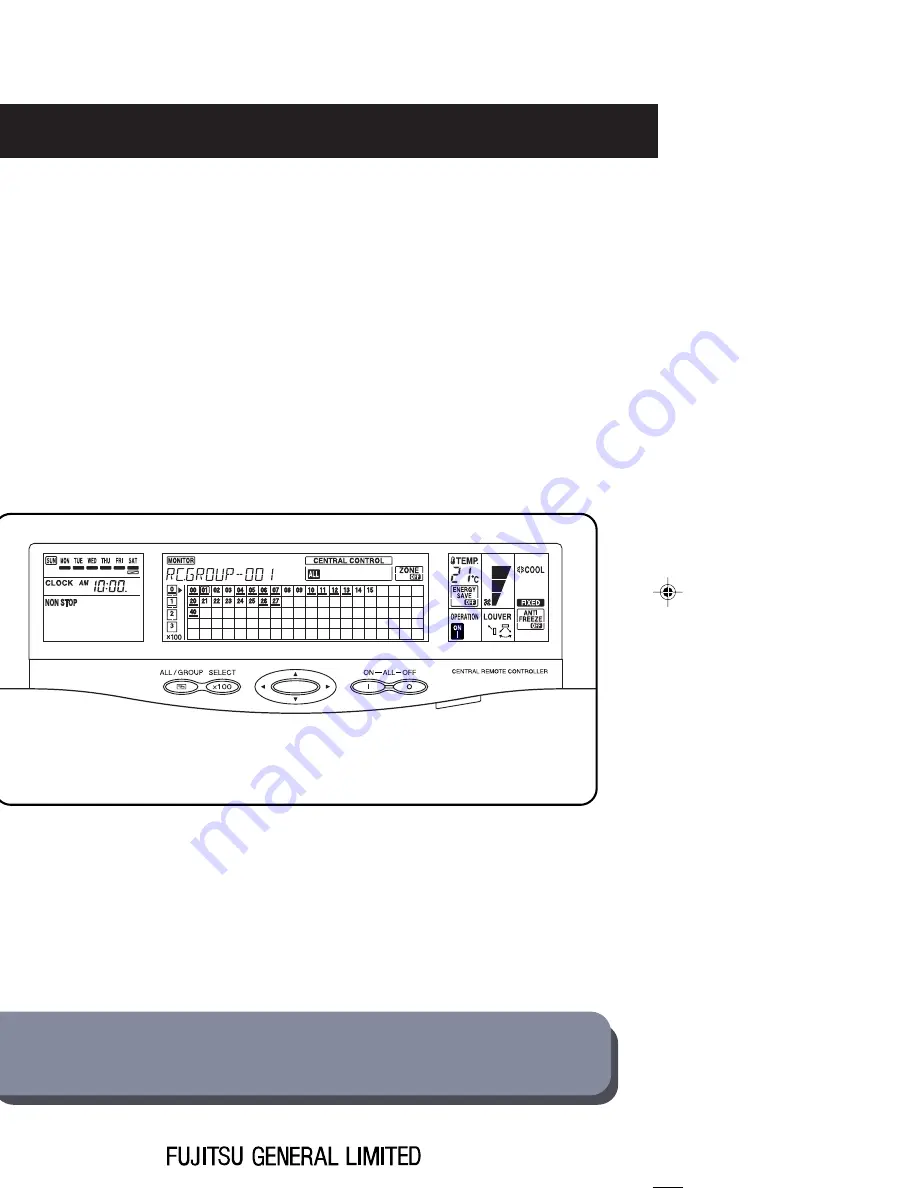
Page 12: ...rating To stop the operation of all indoor units stored in the central remote controller G STATUS DISPLAY H MONITOR DISPLAY I MEMORY DISPLAY J SETTING DISPLAY K ERROR DISPLAY L TRANSMIT INDICATOR DISPLAY M TEST DISPLAY N GROUP CONTROL DISPLAY O CENTRAL CONTROL DISPLAY P FILTER RESET DISPLAY Q ZONE DISPLAY R ALL GROUP BUTTON S SELECT 100 BUTTON T MEMORY BUTTON U MEMORY SETTING BUTTON V CENTRAL CONT...
Page 13: ...he button the current operating condition of the relevant indoor units is shown on the LCD If no action is taken this mode will be shown Control mode Setting screen Control mode is used to set the items to be controlled to the remote control groups that has been stored in the central remote controller There are three control modes in the central remote con troller Individual control mode Used for ...
Page 14: ...13 3 BASIC OPERATION Notes If no action is taken within one minute the screen will always returns to operation display mode automati cally In the control mode use to change to each of the control modes ...
Page 15: ...ollowing sequence to make changes without start ing the unit To stop the operation Select the control mode Change each of the settings Set the power supply to on setting Transmit the newly set information Select the control mode Set the power supply to off setting Transmit the newly set information Notes All the indoor units can be turned on off at the same time with this central remote controller...
Page 16: ...he currently selected central control num ber is displayed In this example the selected control number is 00 The operation display of the remote control group associated with the selected central control num ber is obtained CHECK ACL MASTER ENERGY ANTI FAN TIMER SET TIMER DELETE TIMER DAY CLOCK ADJUST DAY OFF TEMP MEMORY OPERATION MEMORY TEST SET CENTRAL DELETE BACK GROUP ZONE ON OFF TIME CONTROL ...
Page 17: ...umber then go to step 3 When Group control mode is selected use to select the desired group number then go to step 3 When All control mode is selected go directly to step 3 Press the buttons to change the items of setting Refer to 2 4 NAMES AND FUNCTIONS OF THE PARTS for information about the buttons The newly set operation conditions will be applied to the indoor units associated with the central...
Page 18: ...cted If groups are composed of indoor units of HEAT PUMP TYPE refrigerant system will appear on the LCD To be used to change the settings of all remote control groups that have been stored in the cen tral remote controller All control mode Individual control mode Group control mode Notes In order to shorten the setting time as well as to simplify the setting procedure it is possible to send all of...
Page 19: ...g of the selected indoor units P35 Temperature setting Perform the room temperature setting of the selected indoor units P38 Fan speed setting Perform the fan speed setting of the selected indoor units P39 Flow direction setting vertical Adjust the vertical angle of the flaps of the selected indoor units P41 Flow direction setting horizontal Adjust the horizontal angle of the flaps of the selected...
Page 20: ...estrictions on the standard remote controllers as well as the control items on management of the indoor units using the setting buttons in central control area of the central remote controller 4 1 GROUP INFORMATION STORE 20 4 2 STANDARD REMOTE CONTROL OPERATION PROHIBIT SETTING 23 4 3 MEMORY OPERATION 26 4 4 ZONE SETTING 28 4 5 FILTER INDICATOR RESET 30 ...
Page 21: ...with and set by pressing SET Press to select the central control number to be stored in the selected group Press SET to store To continue group information store press BACK to return to the group number selection screen of 1 and repeat steps 2 and 3 To complete the group in formation store press GROUP SETTING in the group selec tion screen shown in step 1 CHECK ACL MASTER ENERGY ANTI FAN TIMER SET...
Page 22: ...ll the central con trol numbers registered in the selected group will be deleted Use to select the central control number in the group selected in step 2 and press DELETE to delete it Repeat step 3 to continue deleting the stored cen tral control number in the same group If you wish to delete the stored information in other group press BACK to return to screen of step 1 Repeat steps 2 and 3 To end...
Page 23: ... groups The following show examples of group formation There are some restrictions on operating mode on display for the following occasions Group formed with the indoor units in two refrigerant systems When part of indoor units exist in cooling heat pump type refrigerant system certain operating mode of the group can not be carried out even if the operating mode is shown on the LCD In addition the...
Page 24: ... remote controller Invalidate or do not able to make ON OFF operation of the indoor units from the relevant standard remote controller Several of the centrally controlling items can be set simultaneously except If is set all operation settings of the relevant standard remote controller invalidate wireless or cannot be made wired The started centrally controlling items can be set only when DIP SW 2...
Page 25: ...ss DELETE to cancel the item The symbol comes on after the setting of the cen trally controlling item Select and all those other symbols will go out because this centrally controlling item includes all those other controlling items by prohibiting all operation settings of standard remote controller Repeat the operations of step 3 and step 4 to per form the desired central control When all the sett...
Page 26: ...ote controller in the system If the set centrally controlling items are not hoped to be removed by setting other central remote controllers please set the DIP SW 2 5 enable disable setting of the standard remote controller prohibition function to disable position It is recommended that only the host central remote controller should be set to enable and the others should be set to disable ...
Page 27: ... SETTING will come on and the unit is in memory operation setting mode In memory operation setting mode the contents of the saved memory operation settings are dis played Press and to check the con tents Press SET and the current operating conditions are saved Press MEMORY SETTING again to end the memory operation setting mode CHECK ACL MASTER ENERGY ANTI FAN TIMER SET TIMER DELETE TIMER DAY CLOCK...
Page 28: ...ry operation The memory operation is performed and the saved operating conditions come on to the display Press MEMORY OPERATION After receiving the necessary data from the central remote controller the indoor unit starts a memory operation ...
Page 29: ...teps 4 5 and notes of 3 3 CONTROL MODE for details CHECK ACL MASTER ENERGY ANTI FAN TIMER SET TIMER DELETE TIMER DAY CLOCK ADJUST DAY OFF TEMP MEMORY OPERATION MEMORY TEST SET CENTRAL DELETE BACK GROUP ZONE ON OFF TIME CONTROL CONTROL FILTER RESET CONTROL FREEZE COPY TIMER MODE SAVE SETTING SETTING 4 4 ZONE SETTING When the ZONE button is pressed the actual operation condition ON or OFF of the sel...
Page 30: ...n is to be ended Refer to 3 3 CONTROL MODE for information about control modes Press ZONE once again will appear It is necessary to transmit the newly set information to the relevant indoor units Refer to steps 4 5 and notes of 3 3 CONTROL MODE for details Note The zone function can be used only with the following indoor units A TFAMF A TFBMF AU TFBMF ...
Page 31: ...displayed needs to be cleaned or exchanged All control mode will flash if the filter of any indoor unit in the system needs to be cleaned or exchanged After the filter has been cleaned or exchanged please reset the filter indicator by Press FILTER RESET will stop flashing and LED SET will light up Press SET to send the filter reset signal to se lected indoor units when the signal transmission Tran...
Page 32: ...peration control area of the central remote controller 5 1 ALL OPERATION ALL STOP 32 5 2 OPERATION STOP 33 5 3 OPERATING MODE SETTING 35 5 4 TEMPERATURE SETTING 38 5 5 FAN SPEED SETTING 39 5 6 FLOW DIRECTION SETTING VERTICAL 41 5 7 FLOW DIRECTION SETTING HORIZONTAL 44 5 8 SWING SETTING 46 5 9 ENERGY SAVE OPERATION SETTING 50 5 10 ANTI FREEZE OPERATION 53 ...
Page 33: ...ill go out 5 1 2 All stop Press will light up An all stop signal will be transmitted in the system immediately A beep sound Beep Be signals the end of the trans mission When the transmission has been completed and will go out CHECK ACL MASTER ENERGY ANTI FAN TIMER SET TIMER DELETE TIMER DAY CLOCK ADJUST DAY OFF TEMP MEMORY OPERATION MEMORY TEST SET CENTRAL DELETE BACK GROUP ZONE ON OFF TIME CONTRO...
Page 34: ...ociated with the se lected central control number Because of the change of the setting LED SET will come on It is necessary to transmit the newly set information to the relevant indoor units Refer to steps 4 5 and notes of 3 3 CONTROL MODE for details CHECK ACL MASTER ENERGY ANTI LOUVER LOUVER FAN TIMER SET TIMER DELETE TIMER DAY CLOCK ADJUST DAY OFF TEMP MEMORY OPERATION MEMORY TEST SET CENTRAL D...
Page 35: ...OL MODE for information about control modes Press ON OFF and will light up The setting is applied to the indoor units associated with the se lected central control number Because of the change of the setting LED SET will come on It is necessary to transmit the newly set information to the relevant indoor units Refer to steps 4 5 and notes of 3 3 CONTROL MODE for details ...
Page 36: ... the indoor units associ ated with the selected central control number Be cause of the change of the setting LED SET will come on It is necessary to transmit the newly set information to the relevant indoor units Refer to steps 4 5 and notes of 3 3 CONTROL MODE for details CHECK ACL MASTER ENERGY ANTI FAN TIMER SET TIMER DELETE TIMER DAY CLOCK ADJUST DAY OFF TEMP MEMORY OPERATION MEMORY TEST SET C...
Page 37: ...e air conditioner selects the appropriate operating mode Cooling or Heating according to the real room temperature When AUTO CHANGE OVER is first selected the fan will operate at very low speed for about one minutes while the unit determines the current conditions of the room and accordingly selects the proper operation mode When the air conditioner has adjusted the room temperature to near the th...
Page 38: ...ring Heating The set thermostat temperature should be higher than the actual room temperature otherwise the heating mode does not work During Cooling The set thermostat temperature should be lower than the actual room temperature otherwise the cooling mode does not work however the fan will rotate in cooling mode ...
Page 39: ... 4 5 and notes of 3 3 CONTROL MODE for details Notes Press to raise the thermostat setting Press to lower the thermostat setting Thermostat setting range AUTO 18 to 30 C Heating 16 to 30 C Cooling Dry 18 to 30 C The thermostat cannot be used to set room temperature during the FAN mode the temperature will not appear on the display of the central remote controller The thermostat setting should be c...
Page 40: ... units associ ated with the selected central control number Be cause of the change of the setting LED SET will come on It is necessary to transmit the newly set information to the relevant indoor units Refer to steps 4 5 and notes of 3 3 CONTROL MODE for details CHECK ACL MASTER ENERGY ANTI FAN TIMER SET TIMER DELETE TIMER DAY CLOCK ADJUST DAY OFF TEMP MEMORY OPERATION MEMORY TEST SET CENTRAL DELE...
Page 41: ... at a very low speed during the monitor operation by which the room tempera ture is deleted Note If fan speed setting is attempted on a cooling heat pump type refrigerant system the central control number will flash and fan operation will not be affected by the settings This occurs when a group is comprised of indoor units which are in different types of refrigerant systems HEAT RECOVERY TYPE HEAT...
Page 42: ...s Press to adjust the flaps angle in order to generate a desired vertical airflow The setting is applied to the indoor units associ ated with the selected central control number Be cause of the change of the setting LED SET will come on Each time the button is pressed the air direction as shown in the display will change as follows 1 2 3 4 CHECK ACL MASTER ENERGY ANTI FAN TIMER SET TIMER DELETE TI...
Page 43: ...the type of operation selected During cooling mode Horizontal flow 1 During heating mode Downward flow 4 The air direction can be adjusted within the range shown below During AUTO mode operation for the first minute after beginning operation airflow will be horizontal flow 1 the air direction cannot be adjusted during this period If the direction setting is set at the same time as operation mode s...
Page 44: ...n During use of the Cooling mode do not set the UP DOWN air direction flap in the 4 position for a long period of time since water vapor may condense near the outlet port and drops of water may drip from the air conditioner When used in a room with infants children elderly or sick persons the air direction and room temperature should be considered carefully when making setting CEILING SUSPENSION T...
Page 45: ... to adjust the flaps angle in order to generate a desired horizontal airflow The setting is applied to the indoor units associ ated with the selected central control number Be cause of the change of the setting LED SET will come on Each time the button is pressed the air direction as shown in the display will change as follows CHECK ACL MASTER ENERGY ANTI FAN TIMER SET TIMER DELETE TIMER DAY CLOCK...
Page 46: ...t is necessary to transmit the newly set information to the relevant indoor units Refer to steps 4 5 and notes of 3 3 CONTROL MODE for details 1 2 3 4 5 CEILING SUSPENSION TYPE FLOOR CONSOLE UNDER CEILING DUAL TYPE WALL MOUNTED TYPE ...
Page 47: ... in the display will change to the In this mode the UP DOWN air direction flaps will swing automatically to direct the airflow both up and down It is necessary to transmit the newly set information to the relevant indoor units Refer to steps 4 5 and notes of 3 3 CONTROL MODE for details CHECK ACL MASTER ENERGY ANTI FAN TIMER SET TIMER DELETE TIMER DAY CLOCK ADJUST DAY OFF TEMP MEMORY OPERATION MEM...
Page 48: ...wly set information to the relevant indoor units Refer to steps 4 5 and notes of 3 3 CONTROL MODE for details About Vertical Airflow Swing Operation The swing range can be adjusted with the remote controller s VERTICAL AIR FLOW DIRECTION SET button The SWING operation may stop temporarily when the air conditioner s fan is not operating or is operating at very low speeds During use of the Cooling m...
Page 49: ...will change to the In this mode the right left air direction flaps will swing automatically to direct the airflow to both the right and the left It is necessary to transmit the newly set information to the relevant indoor units Refer to steps 4 5 and notes of 3 3 CONTROL MODE for details CHECK ACL MASTER ENERGY ANTI FAN TIMER SET TIMER DELETE TIMER DAY CLOCK ADJUST DAY OFF TEMP MEMORY OPERATION ME...
Page 50: ...ress for 2 seconds or more and the shown in the display will change to the It is necessary to transmit the newly set information to the relevant indoor units Refer to steps 4 5 and notes of 3 3 CONTROL MODE for details About Horizontal Airflow Swing Operation The swing range can be adjusted with the remote controller s HORIZONTAL AIR FLOW DIREC TION SET button The SWING operation may stop temporar...
Page 51: ...r information about control modes Press ENERGY SAVE will light up It is necessary to transmit the newly set information to the relevant indoor units Refer to steps 4 5 and notes of 3 3 CONTROL MODE for details CHECK ACL MASTER ENERGY ANTI FAN TIMER SET TIMER DELETE TIMER DAY CLOCK ADJUST DAY OFF TEMP MEMORY OPERATION MEMORY TEST SET CENTRAL DELETE BACK GROUP ZONE ON OFF TIME CONTROL CONTROL FILTER...
Page 52: ...he energy conservation mode ENERGY SAVE raises the set temperature slightly in the cool ing mode and lowers the set temperature in the heating mode using a computer program to economically control the operation of the unit If you press the ENERGY SAVE button while the air conditioner is on it will change to the conser vation mode If you press the ENERGY SAVE button while the unit is in the time mo...
Page 53: ...s When it has lowered a total of 2 C then it will hold the temperature When Cooling After the ENERGY SAVE button is pressed the set temperature will be raised about 0 5 C ev ery 30 minutes When it has lowered a total of 1 C then it will hold the temperature 30 min 0 5 C 1 C Set to the ENERGY SAVE mode 1 C 2 C 30 min Set to the ENERGY SAVE mode ...
Page 54: ...information about control modes Press ANTI FREEZE will come on It is necessary to transmit the newly set information to the relevant indoor units Refer to steps 4 5 and notes of 3 3 CONTROL MODE for details CHECK ACL MASTER ENERGY ANTI FAN TIMER SET TIMER DELETE TIMER DAY CLOCK ADJUST DAY OFF TEMP MEMORY OPERATION MEMORY TEST SET CENTRAL DELETE BACK GROUP ZONE ON OFF TIME CONTROL CONTROL FILTER RE...
Page 55: ...e newly set information to the relevant indoor units Refer to steps 4 5 and notes of 3 3 CONTROL MODE for details About the ANTI FREEZE The ANTI FREEZE operation is only enabled when the indoor unit is in a standby mode waiting for an ON signal from timer or is stopped by ON OFF Whenever the room temperature becomes low it automatically sets the fan to low speed and starts the heating operation Th...
Page 56: ... SETTING METHOD TIMER CONTROL AREA This section explains the methods on timer setting using the buttons in timer control area of the central remote controller 6 1 OFF TIMER 56 6 2 ON TIMER 58 6 3 WEEKLY TIMER 60 6 4 CLOCK SETTING 70 ...
Page 57: ...ndoor units the indoor units will not start to operate If timer settings are performed simultaneously at central remote controllers at multiple locations central remote controller 1 central remote controller 2 the indoor units will follow the command of the central remote controller that the last control signal will send out Stop timer operation An electricity failure will cancel all set time The ...
Page 58: ... is necessary to transmit the newly set information to the relevant indoor units Refer to steps 4 5 and notes of 3 3 CONTROL MODE for details Notes To change the set time during operation Perform steps 1 3 To change the timer mode during operation Perform steps 1 2 To cancel the timer operation Press the TIMER MODE and set the display to in step 2 the indoor units will switch to non stop operation...
Page 59: ...TTING SETTING Enter the control mode to select the central control number the indoor units for the setting Refer to 3 3 CONTROL MODE for information about control modes Press TIMER MODE until the segments of the ap pear on the display Each time the button is pressed the timer function changes in the following order Press TIME to adjust the ON TIMER time Press to advance time Press to reverse time ...
Page 60: ...change the set time during operation Perform steps 1 3 To change the timer mode during operation Perform steps 1 2 To cancel the timer operation Press the TIMER MODE and set the display to in step 2 the indoor units will switch to non stop operation To stop operation during use of timer mode Following the procedures of 5 2 OPERATION STOP to stop the operation of the indoor units ...
Page 61: ...ANTI FAN TIMER SET TIMER DELETE TIMER DAY CLOCK ADJUST DAY OFF TEMP MEMORY OPERATION MEMORY TEST SET CENTRAL DELETE BACK GROUP ZONE ON OFF TIME CONTROL CONTROL FILTER RESET CONTROL FREEZE COPY TIMER MODE SAVE SETTING SETTING Enter the control mode to select the central control number the indoor units to be set Refer to 3 3 CONTROL MODE for information about control modes Press TIMER MODE until the...
Page 62: ...Y1 on time Press to advance time Press to reverse time Press once to move the time 10 minutes Press TIMER DELETE and the currently set time will be deleted Press TIMER SET to store the WEEKLY1 on time As this is done the on time segments stop flashing and the WEEKLY1 OFF time starts flashing Press TIME to adjust the WEEKLY1 off time The earliest OFF time you can set is 10 minutes af ter the ON tim...
Page 63: ...After setting the WEEKLY2 OFF time press the TIMER SET to store the WEEKLY2 OFF time At the moment the setting of WEEKLY2 is also com pleted You will be brought back to the step 4 You can review your setting by pressing TIME Each press moves you to the next setting as follow Press DAY to select another day for set up The procedures are to repeat steps 5 to 10 mentioned above When you have finished...
Page 64: ... 10min Notes A flashing time value indicates that the system is in time setting mode You do not need to set values for both WEEKLY1 and WEEKLY2 If you wish you can set values only for WEEKLY1 or only for WEEKLY2 The allowable range for the day s time setting is shown below If the set OFF time goes into the subsequent day the caption appears on the display ...
Page 65: ...ation To stop weekly timer while leaving the air conditioner running Press TIMER MODE to select NONSTOP To stop weekly timer operation as well as the air conditioner Press ON OFF Refer to 5 2 OPERATION STOP Reviewing Time Settings 1 Press TIMER MODE so that WEEKLY appears on the display 2 Press TIMER SET to select setting mode 3 Press DAY to select the day that you want to check 4 Press TIME to sw...
Page 66: ... TIMER SET to enter the setting mode The WEEKLY1 ON time starts flashing Press TIMER DELETE Then WEEKLY1 setting will be deleted and the time display becomes blank Press TIMER SET to confirm the setting Press DAY to return to step 2 If you wish to delete other time settings repeat 2 to 4 When you have finished setting hold down the TIMER SET for 2 seconds It is necessary to transmit the newly set ...
Page 67: ... times to select the time you want to change The selected setting flashing on the display Each press moves you to the next setting for the selected day as follows WEEKLY1 WEEKLY1 WEEKLY2 WEEKLY2 Step 2 ON OFF ON OFF Press TIME to change time setting Press TIMER SET to confirm the setting Press DAY To return to step 2 If you wish to change other time settings repeat 2 to 4 It is necessary to transm...
Page 68: ... the currently set OFF time If the change would cause a temporary overlap between the first and second ON OFF time 6 3 5 Copying the selected time setting Carry out steps 1 to 3 of the Setting up the weekly timer operation procedure Press DAY to select the day that you want to copy the timer setting ON OFF ON OFF WEEKLY 1 WEEKLY 1 Change Time Time Temporary overlap Change ON OFF WEEKLY 1 ON OFF WE...
Page 69: ...5 you can copy the time setting you want and paste it to the day you want to set Notes The WEEKLY1 WEEKLY2 timer settings that have been set for other days can be pasted to another day by using the copy paste function In the one week setting for the weekly timer if even a single day setting overlaps into the next day this function cannot be used 6 3 6 Using the day OFF setting Use the DAY OFF sett...
Page 70: ...to steps 4 5 and notes of 3 3 CONTROL MODE for details Notes The DAY OFF setting is only available for days for which weekly time settings already exist You can make this setting for any of the next seven days counting from current day The DAY OFF setting is effective over the range illustrated below The weekly setting for which an ON time has been set is eligible for the day in which the DAY OFF ...
Page 71: ...Press TIME and set the current time CHECK ACL MASTER ENERGY ANTI FAN TIMER SET TIMER DELETE TIMER DAY CLOCK ADJUST DAY OFF TEMP MEMORY OPERATION MEMORY TEST SET CENTRAL DELETE BACK GROUP ZONE ON OFF TIME CONTROL CONTROL FILTER RESET CONTROL FREEZE COPY TIMER MODE SAVE SETTING SETTING 6 4 CLOCK SETTING The clock setting can be used to set the current time or set various operations of the central re...
Page 72: ...nd set the beep enable disable set ting Finally press CLOCK ADJUST to end the clock setting Note If there is an indoor unit that is operating based on the timer of the central remote controller The operations of the time setting mention above will be limited to steps 2 and 6 ...
Page 73: ...72 6 TIMER SETTING METHOD ...
Page 74: ...7 ERROR DISPLAY 7 ERROR DISPLAY This section explains Error display of the central re mote controller 7 1 ERROR MONITOR 74 7 2 ERROR CODES 76 7 3 ALL CLEAR SWITCH 77 ...
Page 75: ...te controller group Press CHECK to start the error monitor The LCD changes to the error monitor screen Press to select the central control number for which its details of the error contents are to be confirmed The number of the caus ing the error is flashing Press to select the display mode for the error code Each press of will switch the display as shown below Current error code First previous er...
Page 76: ...the error monitor Outdoor unit addresses are displayed as follows Master 0 Slave1 1 Slave2 2 Slave3 3 TIME TIME TIME Indoor unit error display Outdoor unit error display Central remote control error display Refrigerant system address Error code Indoor unit address Refrigerant system address Error code Outdoor unit address Error code Central remote controller address ...
Page 77: ...emperature thermistor error Heat exchanger inlet thermistor 1 error Heat exchanger inlet thermistor 2 error Heat exchanger inlet thermistor 3 error Heat exchanger outlet thermistor 1 error Heat exchanger outlet thermistor 2 error Heat exchanger outlet thermistor 3 error Suction temperature thermistor error Discharge pressure sensor error Liquid pressure sensor error Suction pressure sensor error O...
Page 78: ...emote controller CHECK ACL MASTER ENERGY ANTI FAN TIMER SET TIMER DELETE TIMER DAY CLOCK ADJUST DAY OFF TEMP MEMORY OPERATION MEMORY TEST SET CENTRAL DELETE BACK GROUP ZONE ON OFF TIME CONTROL CONTROL FILTER RESET CONTROL FREEZE COPY TIMER MODE SAVE SETTING SETTING ACL Switch ...
Page 79: ...78 7 ERROR DISPLAY ...
Page 80: ...8 SPECIFICATIONS 8 SPECIFICATIONS This section explains the specifications and dimen sions of the central remote controller 8 1 SPECIFICATIONS 80 8 2 DIMENSIONS 80 ...
Page 81: ...on adapter Supply power 50 60 Hz 220 240 V Power consumption W 4 8 W Size H W D mm 143 296 22 107 288 100 Weight g 550 1300 8 2 DIMENSIONS 143 296 22 Front View Side View Rear View 1 2 220 240V POWER 1 2 TRANS MISSION 100 106 6 243 OPERATION PANEL TRANSMISSION ADAPTOR ...
Page 82: ......