SK-96380-120PMT User Guide
Chapter 3 Jumpers and Switches
© Fujitsu Microelectronics Europe GmbH
- 19 -
FMEMCU-UG-960001-15
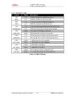
3.4.2 LIN-UART 2 (X9):
Jumper
Setting
Description
1-2
SIN2 is connected to RS232 transceiver
JP37
(RXD)
2-3
SIN2 is connected to LIN transceiver
1-2
SOT2 is connected to RS232 transceiver
JP57
(TXD)
2-3
SOT2 is connected to LIN transceiver
1-2
X9 Pin2 is connected to RS232 transceiver (T1out)
JP40
(RS232/LIN)
2-3
X9 Pin2 is connected to LIN transceiver (BUS)
Closed
RTS and CTS of X9 are connected
JP36
(RTS-CTS)
Open
RTS and CTS of X9 are not connected
1-2
DTR signal (Pin 6 of X9) is used as reset source
JP38
(DTR/RTS)
2-3
RTS signal (Pin 7 of X9) is used as reset source
Closed
LIN transceiver for X5 is enabled
JP43
(LIN enable)
Open
LIN transceiver for X5 is disabled
Closed
LIN-UART2 is LIN Master
JP45
(LIN master)
Open
LIN-UART2 is LIN Slave
Closed
Pin 1 (LIN Vs) of X9 is connected to Vin
JP42
(LIN Vbat)
Open
Pin 1 (LIN Vs) of X9 is not connected to Vin
Table 3-6: UART2 Settings

